4 nwait latency and read/write timings – Rainbow Electronics AT91CAP9S250A User Manual
Page 198
198
6264A–CAP–21-May-07
AT91CAP9S500A/AT91CAP9S250A
22.11.4
NWAIT Latency and Read/write Timings
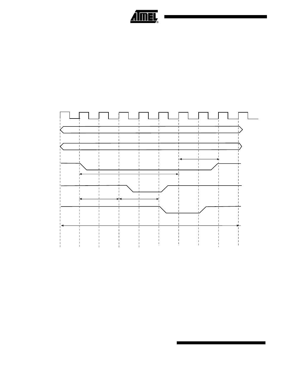
There may be a latency between the assertion of the read/write controlling signal and the asser-
tion of the NWAIT signal by the device. The programmed pulse length of the read/write
controlling signal must be at least equal to this latency plus the 2 cycles of resynchronization + 1
cycle. Otherwise, the SMC may enter the hold state of the access without detecting the NWAIT
signal assertion. This is true in frozen mode as well as in ready mode. This is illustrated on
.
When EXNW_MODE is enabled (ready or frozen), the user must program a pulse length of the
read and write controlling signal of at least:
minimal pulse length = NWAIT latency + 2 resynchronization cycles + 1 cycle
Figure 22-30. NWAIT Latency
EXNW_MODE = 10 or 11
READ_MODE = 1 (NRD_controlled)
NRD_PULSE = 5
A
[25:2]
MCK
NRD
4
3
2
1
0
0
0
Read cycle
minimal pulse length
NWAIT latency
NWAIT
intenally synchronized
NWAIT signal
WAIT STATE
2 cycle resynchronization
NBS0, NBS1,
NBS2, NBS3,
A0,A1