3 typical connection, 4 functional description, 1 usb v2.0 high speed device port introduction – Rainbow Electronics AT91CAP9S250A User Manual
Page 849: 2 usb v2.0 high speed transfer types
849
6264A–CAP–21-May-07
AT91CAP9S500A/AT91CAP9S250A
44.3
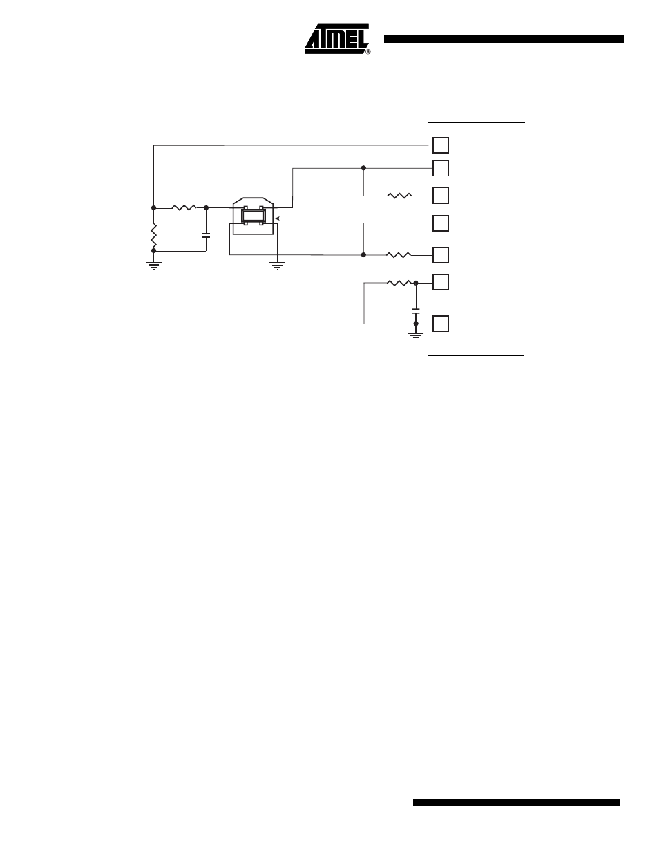
Typical Connection
Figure 44-2. Board Schematic
Note:
The values shown on the 22 k
Ω
and 15 k
Ω
resistors are only valid with 3V3 supplied PIOs.
44.4
Functional Description
44.4.1
USB V2.0 High Speed Device Port Introduction
The USB V2.0 High Speed Device Port provides communication services between host and
attached USB devices. Each device is offered with a collection of communication flows (pipes)
associated with each endpoint. Software on the host communicates with a USB Device through
a set of communication flows.
44.4.2
USB V2.0 High Speed Transfer Types
A communication flow is carried over one of four transfer types defined by the USB device.
A device provides several logical communication pipes with the host. To each logical pipe is
associated an endpoint. Transfer through a pipe belongs to one of the four transfer types:
• Control Transfers: Used to configure a device at attach time and can be used for other device-
specific purposes, including control of other pipes on the device.
• Bulk Data Transfers: Generated or consumed in relatively large burst quantities and have
wide dynamic latitude in transmission constraints.
• Interrupt Data Transfers: Used for timely but reliable delivery of data, for example, characters
or coordinates with human-perceptible echo or feedback response characteristics.
• Isochronous Data Transfers: Occupy a prenegotiated amount of USB bandwidth with a
prenegotiated delivery latency. (Also called streaming real time transfers.)
As indicated below, transfers are sequential events carried out on the USB bus.
Endpoints must be configured according to the transfer type they handle.
6K8
PIO (VBUS DETECT)
DHSDP
DHSDM
DFSDM
DFSDP
VBG
GND
C
RPB
:1µF to 10µF
C
RPB
1
4
2
3
39
39
10 pF
"B" Receptacle
1 = VBUS
2 = D-
3 = D+
4 = GND
Ω
Ω
Ω
Ω
Shell = Shield
15k
22k
(1)
(1)