3 application block diagram, 4 i/o lines description, 5 product dependencies – Rainbow Electronics AT91CAP9S250A User Manual
Page 683: 1 i/o lines, 2 power management, 3 interrupt, Implementation layers
683
6264A–CAP–21-May-07
AT91CAP9S500A/AT91CAP9S250A
39.3
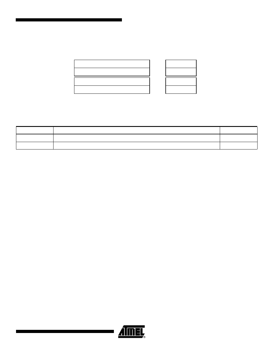
Application Block Diagram
Figure 39-2. Application Block Diagram
39.4
I/O Lines Description
39.5
Product Dependencies
39.5.1
I/O Lines
The pins used for interfacing the CAN may be multiplexed with the PIO lines. The programmer
must first program the PIO controller to assign the desired CAN pins to their peripheral func-
tion. If I/O lines of the CAN are not used by the application, they can be used for other
purposes by the PIO Controller.
39.5.2
Power Management
The programmer must first enable the CAN clock in the Power Management Controller (PMC)
before using the CAN.
A Low-power Mode is defined for the CAN controller: If the application does not require CAN
operations, the CAN clock can be stopped when not needed and be restarted later. Before
stopping the clock, the CAN Controller must be in Low-power Mode to complete the current
transfer. After restarting the clock, the application must disable the Low-power Mode of the
CAN controller.
39.5.3
Interrupt
The CAN interrupt line is connected on one of the internal sources of the Advanced Interrupt
Controller. Using the CAN interrupt requires the AIC to be programmed first. Note that it is not
recommended to use the CAN interrupt line in edge-sensitive mode.
Software
Software
CAN Controller
Transceiver
Implementation
Layers
CAN-based Application Layer
CAN-based Profiles
CAN Data Link Layer
CAN Physical Layer
Table 39-1.
I/O Lines Description
Name
Description
Type
CANRX
CAN Receive Serial Data
Input
CANTX
CAN Transmit Serial Data
Output