Reset controller (rstc), 1 description, 2 block diagram – Rainbow Electronics AT91CAP9S250A User Manual
Page 85: 3 functional description, 1 reset controller overview
85
6264A–CAP–21-May-07
AT91CAP9S500A/AT91CAP9S250A
15. Reset Controller (RSTC)
15.1
Description
The Reset Controller (RSTC), based on power-on reset cells, handles all the resets of the sys-
tem without any external components. It reports which reset occurred last.
The Reset Controller also drives independently or simultaneously the external reset and the
peripheral and processor resets.
15.2
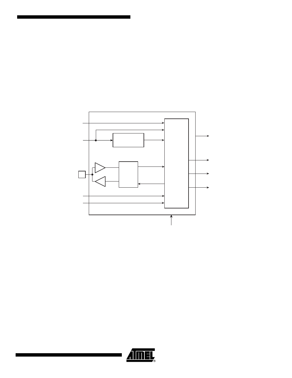
Block Diagram
Figure 15-1. Reset Controller Block Diagram
15.3
Functional Description
15.3.1
Reset Controller Overview
The Reset Controller is made up of an NRST Manager, a Startup Counter and a Reset State
Manager. It runs at Slow Clock and generates the following reset signals:
• proc_nreset: Processor reset line. It also resets the Watchdog Timer.
• backup_nreset: Affects all the peripherals powered by VDDBU.
• periph_nreset: Affects the whole set of embedded peripherals.
• nrst_out: Drives the NRST pin.
These reset signals are asserted by the Reset Controller, either on external events or on soft-
ware action. The Reset State Manager controls the generation of reset signals and provides a
signal to the NRST Manager when an assertion of the NRST pin is required.
The NRST Manager shapes the NRST assertion during a programmable time, thus controlling
external device resets.
NRST
Startup
Counter
proc_nreset
wd_fault
periph_nreset
backup_neset
SLCK
Reset
State
Manager
Reset Controller
rstc_irq
NRST
Manager
exter_nreset
nrst_out
Main Supply
POR
WDRPROC
user_reset
Backup Supply
POR