2 reset controller, 3 shutdown controller, 4 clock generator – Rainbow Electronics AT91CAP9S250A User Manual
Page 29
29
6264A–CAP–21-May-07
AT91CAP9S500A/AT91CAP9S250A
9.2
Reset Controller
• Based on two Power-on-Reset cells
– One on VDDBU and one on VDDCORE
• Status of the last reset
– Either general reset (VDDBU rising), wake-up reset (VDDCORE rising), software
reset, user reset or watchdog reset
• Controls the internal resets and the NRST pin output
– Allows shaping a reset signal for the external devices
9.3
Shutdown Controller
• Shutdown and Wake-Up logic
– Software programmable assertion of the SHDN pin
– Deassertion Programmable on a WKUP pin level change or on alarm
9.4
Clock Generator
• Embeds the low power 32,768 Hz Slow Clock Oscillator
– Provides the permanent Slow Clock SLCK to the system
• Embeds the Main Oscillator
– Oscillator bypass feature
– Supports 8 to 16 MHz crystals
– 12 MHz crystal is required for USB High-Speed Device
• Embeds 2 PLLs
– Output 80 to 200 MHz clocks
– Integrates an input divider to increase output accuracy
– 1 MHz minimum input frequency
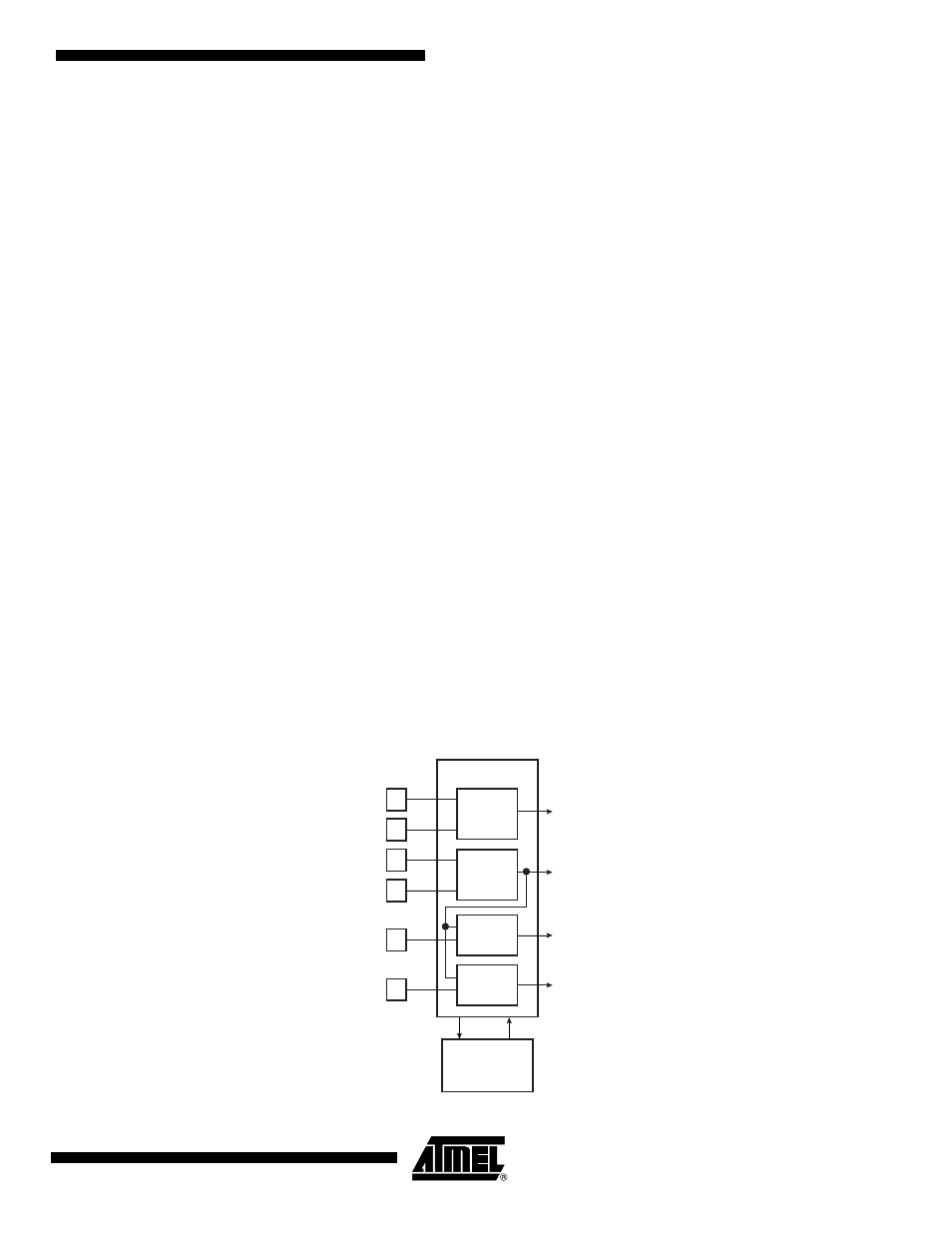
Figure 9-2.
Clock Generator Block Diagram
Power
Management
Controller
XIN
XOUT
PLLRCA
Slow Clock
SLCK
Main Clock
MAINCK
PLLA Clock
PLLACK
Control
Status
PLL and
Divider B
PLLRCB
PLLB Clock
PLLBCK
XIN32
XOUT32
Slow Clock
Oscillator
Main
Oscillator
PLL and
Divider A
Clock Generator