1 twi control register – Rainbow Electronics AT91CAP9S250A User Manual
Page 511
511
6264A–CAP–21-May-07
AT91CAP9S500A/AT91CAP9S250A
34.10.1
TWI Control Register
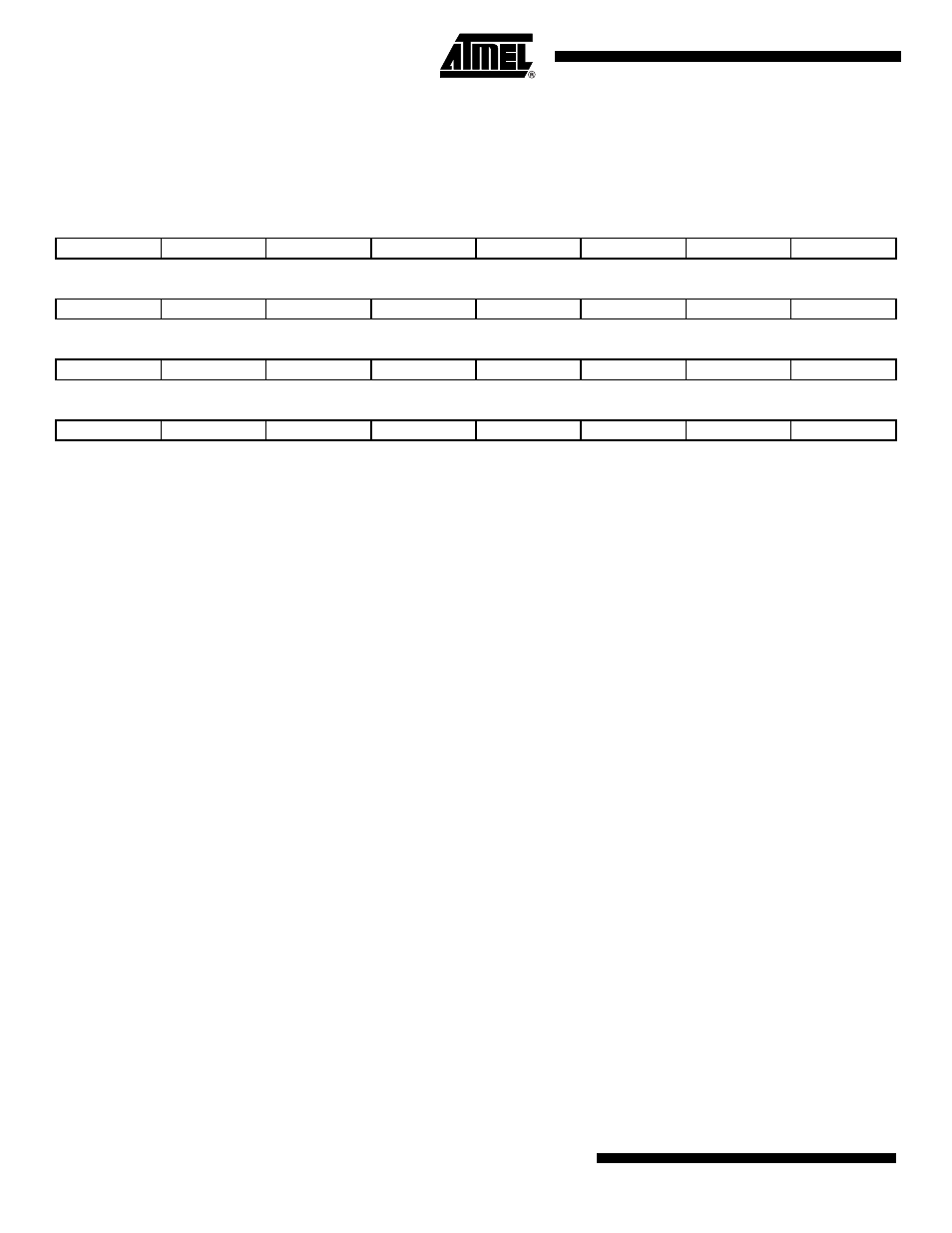
Name: TWI_CR
Access: Write-only
Reset Value: 0x00000000
• START: Send a START Condition
0 = No effect.
1 = A frame beginning with a START bit is transmitted according to the features defined in the mode register.
This action is necessary when the TWI peripheral wants to read data from a slave. When configured in Master Mode with a
write operation, a frame is sent as soon as the user writes a character in the Transmit Holding Register (TWI_THR).
• STOP: Send a STOP Condition
0 = No effect.
1 = STOP Condition is sent just after completing the current byte transmission in master read mode.
– In single data byte master read, the START and STOP must both be set.
– In multiple data bytes master read, the STOP must be set after the last data received but one.
– In master read mode, if a NACK bit is received, the STOP is automatically performed.
– In multiple data write operation, when both THR and shift register are empty, a STOP condition is automatically
sent.
• MSEN: TWI Master Mode Enabled
0 = No effect.
1 = If MSDIS = 0, the master mode is enabled.
Note:
Switching from Slave to Master mode is only permitted when TXCOMP = 1.
• MSDIS: TWI Master Mode Disabled
0 = No effect.
1 = The master mode is disabled, all pending data is transmitted. The shifter and holding characters (if it contains data) are
transmitted in case of write operation. In read operation, the character being transferred must be completely received
before disabling.
• SVEN: TWI Slave Mode Enabled
0 = No effect.
31
30
29
28
27
26
25
24
–
–
–
–
–
–
–
–
23
22
21
20
19
18
17
16
–
–
–
–
–
–
–
–
15
14
13
12
11
10
9
8
–
–
–
–
–
–
–
–
7
6
5
4
3
2
1
0
SWRST
–
SVDIS
SVEN
MSDIS
MSEN
STOP
START