6 user interface – Rainbow Electronics AT91CAP9S250A User Manual
Page 439
439
6264A–CAP–21-May-07
AT91CAP9S500A/AT91CAP9S250A
• Four output signals on I/O lines 4 to 7 (to drive LEDs for example), driven high and low, no
pull-up resistor
• Four input signals on I/O lines 8 to 11 (to read push-button states for example), with pull-up
resistors, glitch filters and input change interrupts
• Four input signals on I/O line 12 to 15 to read an external device status (polled, thus no input
change interrupt), no pull-up resistor, no glitch filter
• I/O lines 16 to 19 assigned to peripheral A functions with pull-up resistor
• I/O lines 20 to 23 assigned to peripheral B functions, no pull-up resistor
• I/O line 24 to 27 assigned to peripheral A with Input Change Interrupt and pull-up resistor
32.6
User Interface
Each I/O line controlled by the PIO Controller is associated with a bit in each of the PIO Control-
ler User Interface registers. Each register is 32 bits wide. If a parallel I/O line is not defined,
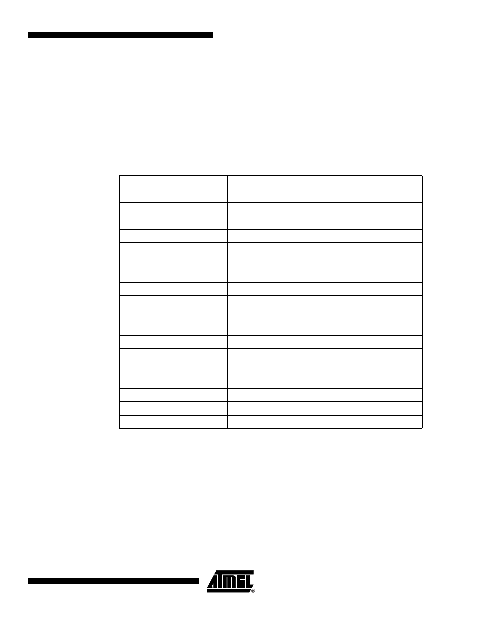
Table 32-1.
Programming Example
Register
Value to be Written
PIO_PER
0x0000 FFFF
PIO_PDR
0x0FFF 0000
PIO_OER
0x0000 00FF
PIO_ODR
0x0FFF FF00
PIO_IFER
0x0000 0F00
PIO_IFDR
0x0FFF F0FF
PIO_SODR
0x0000 0000
PIO_CODR
0x0FFF FFFF
PIO_IER
0x0F00 0F00
PIO_IDR
0x00FF F0FF
PIO_MDER
0x0000 000F
PIO_MDDR
0x0FFF FFF0
PIO_PUDR
0x00F0 00F0
PIO_PUER
0x0F0F FF0F
PIO_ASR
0x0F0F 0000
PIO_BSR
0x00F0 0000
PIO_OWER
0x0000 000F
PIO_OWDR
0x0FFF FFF0