Rainbow Electronics AT91CAP9S250A User Manual
Page 411
411
6264A–CAP–21-May-07
AT91CAP9S500A/AT91CAP9S250A
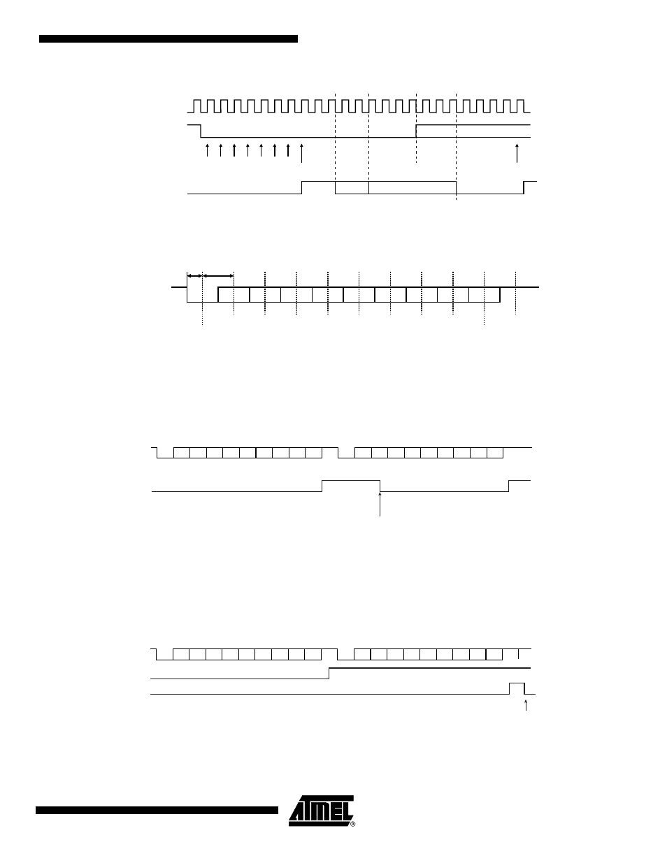
Figure 31-4. Start Bit Detection
Figure 31-5. Character Reception
31.4.2.3
Receiver Ready
When a complete character is received, it is transferred to the DBGU_RHR and the RXRDY sta-
tus bit in DBGU_SR (Status Register) is set. The bit RXRDY is automatically cleared when the
receive holding register DBGU_RHR is read.
Figure 31-6. Receiver Ready
31.4.2.4
Receiver Overrun
If DBGU_RHR has not been read by the software (or the Peripheral Data Controller) since the
last transfer, the RXRDY bit is still set and a new character is received, the OVRE status bit in
DBGU_SR is set. OVRE is cleared when the software writes the control register DBGU_CR with
the bit RSTSTA (Reset Status) at 1.
Figure 31-7. Receiver Overrun
31.4.2.5
Parity Error
Each time a character is received, the receiver calculates the parity of the received data bits, in
accordance with the field PAR in DBGU_MR. It then compares the result with the received parity
Sampling Clock
DRXD
True Start
Detection
D0
Baud Rate
Clock
D0
D1
D2
D3
D4
D5
D6
D7
DRXD
True Start Detection
Sampling
Parity Bit
Stop Bit
Example: 8-bit, parity enabled 1 stop
1 bit
period
0.5 bit
period
D0
D1
D2
D3
D4
D5
D6
D7
P
S
S
D0
D1
D2
D3
D4
D5
D6
D7
P
DRXD
Read DBGU_RHR
RXRDY
D0
D1
D2
D3
D4
D5
D6
D7
P
S
S
D0
D1
D2
D3
D4
D5
D6
D7
P
DRXD
RSTSTA
RXRDY
OVRE
stop
stop