Rainbow Electronics AT91CAP9S250A User Manual
Page 554
554
6264A–CAP–21-May-07
AT91CAP9S500A/AT91CAP9S250A
35.6.5.1
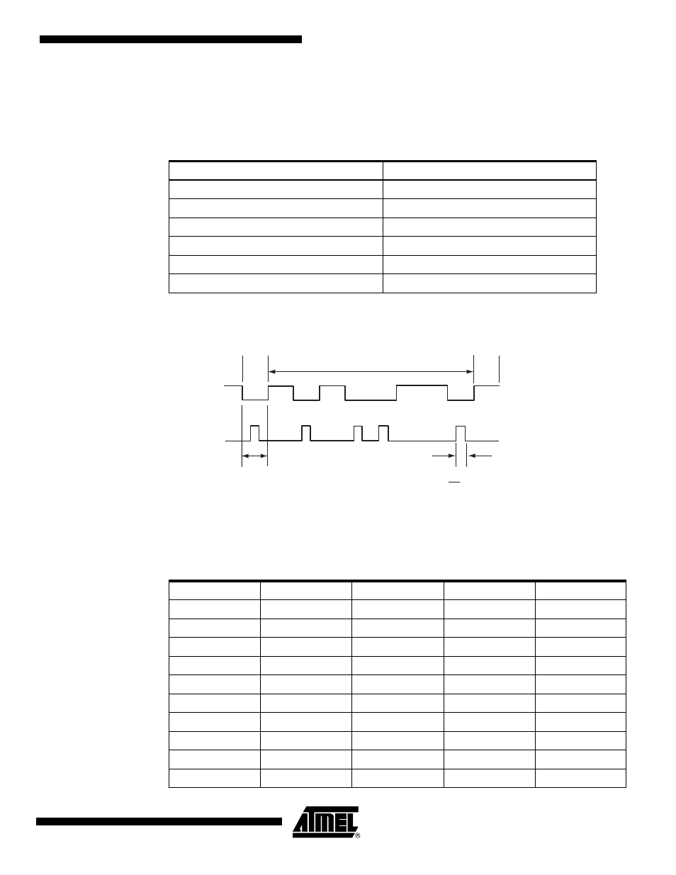
IrDA Modulation
For baud rates up to and including 115.2 Kbits/sec, the RZI modulation scheme is used. “0” is
represented by a light pulse of 3/16th of a bit time. Some examples of signal pulse duration are
shown in
shows an example of character transmission.
Figure 35-34. IrDA Modulation
35.6.5.2
IrDA Baud Rate
gives some examples of CD values, baud rate error and pulse duration. Note that
the requirement on the maximum acceptable error of ±1.87% must be met.
Table 35-9.
IrDA Pulse Duration
Baud Rate
Pulse Duration (3/16)
2.4 Kb/s
78.13 µs
9.6 Kb/s
19.53 µs
19.2 Kb/s
9.77 µs
38.4 Kb/s
4.88 µs
57.6 Kb/s
3.26 µs
115.2 Kb/s
1.63 µs
Bit Period
Bit Period
3
16
Start
Bit
Data Bits
Stop
Bit
0
0
0
0
0
1
1
1
1
1
Transmitter
Output
TXD
Table 35-10. IrDA Baud Rate Error
Peripheral Clock
Baud Rate
CD
Baud Rate Error
Pulse Time
3 686 400
115 200
2
0.00%
1.63
20 000 000
115 200
11
1.38%
1.63
32 768 000
115 200
18
1.25%
1.63
40 000 000
115 200
22
1.38%
1.63
3 686 400
57 600
4
0.00%
3.26
20 000 000
57 600
22
1.38%
3.26
32 768 000
57 600
36
1.25%
3.26
40 000 000
57 600
43
0.93%
3.26
3 686 400
38 400
6
0.00%
4.88
20 000 000
38 400
33
1.38%
4.88