12 pwm channel counter register, 13 pwm channel update register – Rainbow Electronics AT91CAP9S250A User Manual
Page 757
757
6264A–CAP–21-May-07
AT91CAP9S500A/AT91CAP9S250A
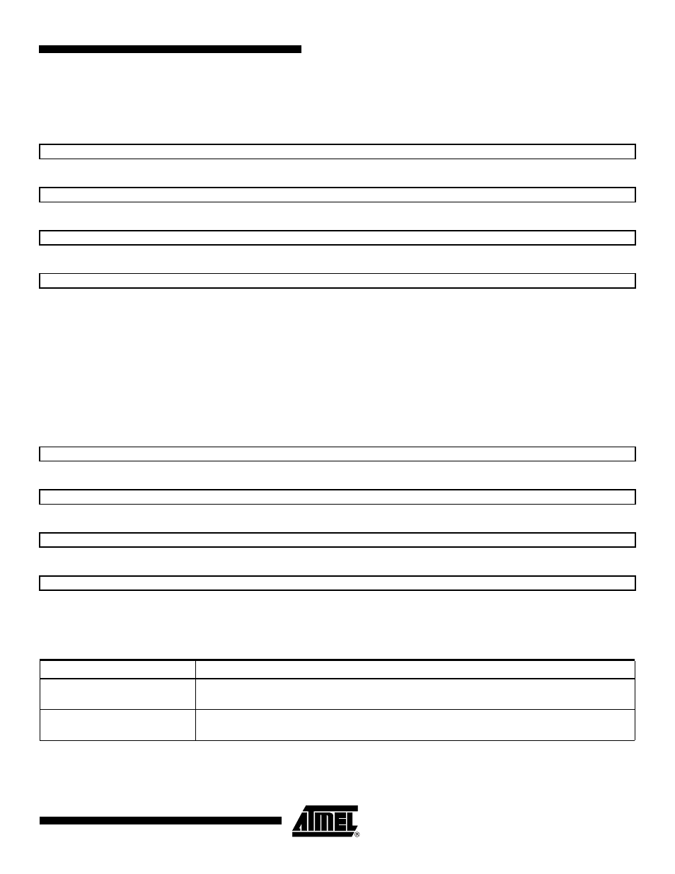
40.6.12
PWM Channel Counter Register
Register Name:
PWM_CCNTx
Access Type:
Read-only
• CNT: Channel Counter Register
Internal counter value. This register is reset when:
• the channel is enabled (writing CHIDx in the PWM_ENA register).
• the counter reaches CPRD value defined in the PWM_CPRDx register if the waveform is left aligned.
40.6.13
PWM Channel Update Register
Register Name:
PWM_CUPDx
Access Type:
Write-only
This register acts as a double buffer for the period or the duty cycle. This prevents an unexpected waveform when modify-
ing the waveform period or duty-cycle.
Only the first 16 bits (internal channel counter size) are significant.
31
30
29
28
27
26
25
24
CNT
23
22
21
20
19
18
17
16
CNT
15
14
13
12
11
10
9
8
CNT
7
6
5
4
3
2
1
0
CNT
31
30
29
28
27
26
25
24
CUPD
23
22
21
20
19
18
17
16
CUPD
15
14
13
12
11
10
9
8
CUPD
7
6
5
4
3
2
1
0
CUPD
CPD (PWM_CMRx Register)
0
The duty-cycle (CDTC in the PWM_CDRx register) is updated with the CUPD value at the
beginning of the next period.
1
The period (CPRD in the PWM_CPRx register) is updated with the CUPD value at the beginning
of the next period.