6 functional description, 1 transfer format, 2 modes of operation – Rainbow Electronics AT91CAP9S250A User Manual
Page 486
486
6264A–CAP–21-May-07
AT91CAP9S500A/AT91CAP9S250A
34.6
Functional Description
34.6.1
Transfer Format
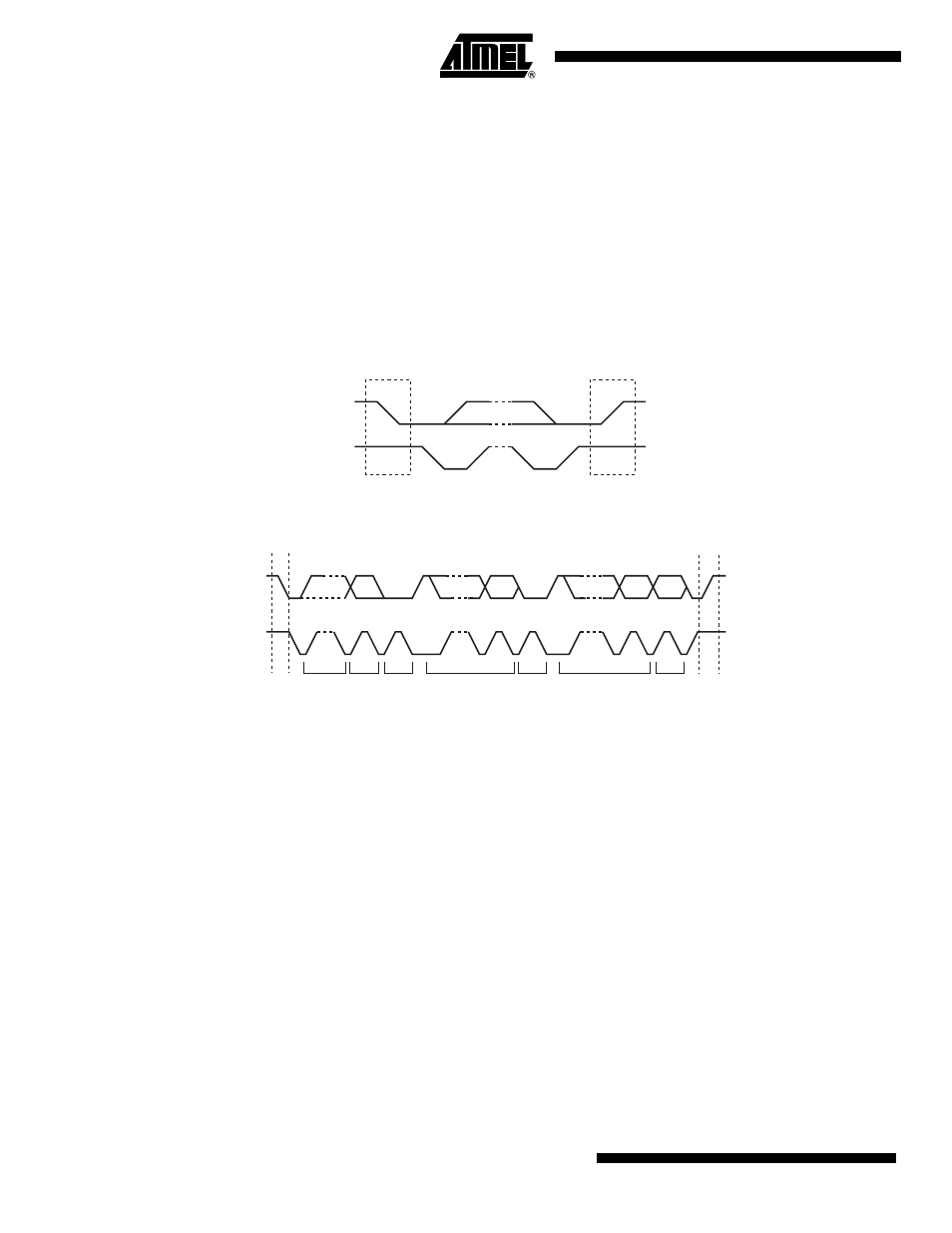
The data put on the TWD line must be 8 bits long. Data is transferred MSB first; each byte must
be followed by an acknowledgement. The number of bytes per transfer is unlimited (see
Each transfer begins with a START condition and terminates with a STOP condition (see
• A high-to-low transition on the TWD line while TWCK is high defines the START condition.
• A low-to-high transition on the TWD line while TWCK is high defines a STOP condition.
Figure 34-3. START and STOP Conditions
Figure 34-4. Transfer Format
34.6.2
Modes of Operation
The TWI has six modes of operations:
• Master transmitter mode
• Master receiver mode
• Multi-master transmitter mode
• Multi-master receiver mode
• Slave transmitter mode
• Slave receiver mode
These modes are described in the following chapters.
TWD
TWCK
Start
Stop
TWD
TWCK
Start
Address
R/W
Ack
Data
Ack
Data
Ack
Stop