Rainbow Electronics AT91CAP9S250A User Manual
Page 530
530
6264A–CAP–21-May-07
AT91CAP9S500A/AT91CAP9S250A
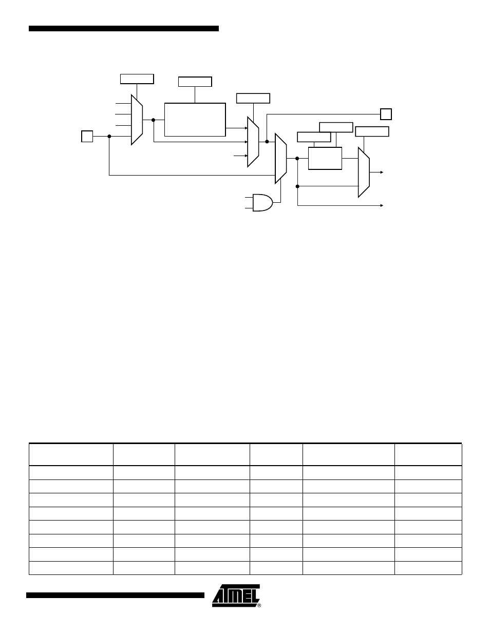
Figure 35-3. Baud Rate Generator
35.6.1.1
Baud Rate in Asynchronous Mode
If the USART is programmed to operate in asynchronous mode, the selected clock is first
divided by CD, which is field programmed in the Baud Rate Generator Register (US_BRGR).
The resulting clock is provided to the receiver as a sampling clock and then divided by 16 or 8,
depending on the programming of the OVER bit in US_MR.
If OVER is set to 1, the receiver sampling is 8 times higher than the baud rate clock. If OVER is
cleared, the sampling is performed at 16 times the baud rate clock.
The following formula performs the calculation of the Baud Rate.
This gives a maximum baud rate of MCK divided by 8, assuming that MCK is the highest possi-
ble clock and that OVER is programmed at 1.
Baud Rate Calculation Example
shows calculations of CD to obtain a baud rate at 38400 bauds for different source
clock frequencies. This table also shows the actual resulting baud rate and the error.
MCK/DIV
16-bit Counter
0
Baud Rate
Clock
CD
CD
Sampling
Divider
0
1
>1
Sampling
Clock
Reserved
MCK
SCK
USCLKS
OVER
SCK
SYNC
SYNC
USCLKS = 3
1
0
2
3
0
1
0
1
FIDI
Baudrate
SelectedClock
8 2
Over
–
(
)
CD
(
)
--------------------------------------------
=
Table 35-2.
Baud Rate Example (OVER = 0)
Source Clock
Expected Baud
Rate
Calculation Result
CD
Actual Baud Rate
Error
MHz
Bit/s
Bit/s
3 686 400
38 400
6.00
6
38 400.00
0.00%
4 915 200
38 400
8.00
8
38 400.00
0.00%
5 000 000
38 400
8.14
8
39 062.50
1.70%
7 372 800
38 400
12.00
12
38 400.00
0.00%
8 000 000
38 400
13.02
13
38 461.54
0.16%
12 000 000
38 400
19.53
20
37 500.00
2.40%
12 288 000
38 400
20.00
20
38 400.00
0.00%