3 write waveforms – Rainbow Electronics AT91CAP9S250A User Manual
Page 180
180
6264A–CAP–21-May-07
AT91CAP9S500A/AT91CAP9S250A
22.8.3
Write Waveforms
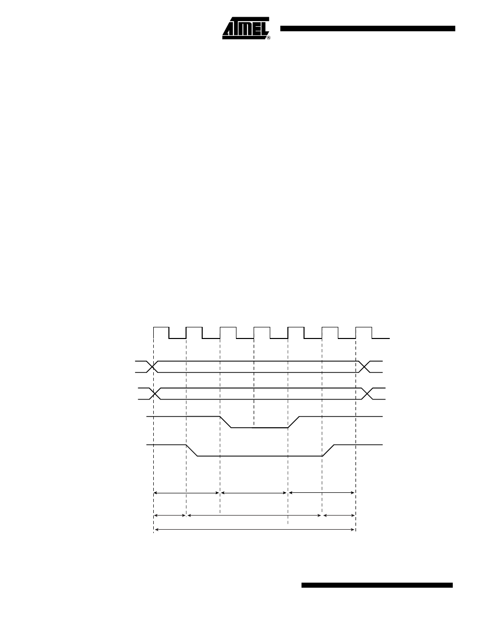
The write protocol is similar to the read protocol. It is depicted in
starts with the address setting on the memory address bus.
22.8.3.1
NWE Waveforms
The NWE signal is characterized by a setup timing, a pulse width and a hold timing.
1.
NWE_SETUP: the NWE setup time is defined as the setup of address and data before
the NWE falling edge;
2.
NWE_PULSE: The NWE pulse length is the time between NWE falling edge and NWE
rising edge;
3.
NWE_HOLD: The NWE hold time is defined as the hold time of address and data after
the NWE rising edge.
The NWE waveforms apply to all byte-write lines in Byte Write access mode: NWR0 to NWR3.
22.8.3.2
NCS Waveforms
The NCS signal waveforms in write operation are not the same that those applied in read opera-
tions, but are separately defined:
1.
NCS_WR_SETUP: the NCS setup time is defined as the setup time of address before
the NCS falling edge.
2.
NCS_WR_PULSE: the NCS pulse length is the time between NCS falling edge and
NCS rising edge;
3.
NCS_WR_HOLD: the NCS hold time is defined as the hold time of address after the
NCS rising edge.
Figure 22-12. Write Cycle
A
[25:2]
NBS0, NBS1,
NBS2, NBS3,
A0, A1
NCS
NWE_SETUP
NWE_PULSE
NWE_HOLD
MCK
NWE
NCS_WR_SETUP
NCS_WR_PULSE
NCS_WR_HOLD
NWE_CYCLE