4 peripheral data controller – Rainbow Electronics AT91CAP9S250A User Manual
Page 413
413
6264A–CAP–21-May-07
AT91CAP9S500A/AT91CAP9S250A
PARE in the mode register DBGU_MR defines whether or not a parity bit is shifted out. When a
parity bit is enabled, it can be selected between an odd parity, an even parity, or a fixed space or
mark bit.
Figure 31-10. Character Transmission
31.4.3.3
Transmitter Control
When the transmitter is enabled, the bit TXRDY (Transmitter Ready) is set in the status register
DBGU_SR. The transmission starts when the programmer writes in the Transmit Holding Regis-
ter DBGU_THR, and after the written character is transferred from DBGU_THR to the Shift
Register. The bit TXRDY remains high until a second character is written in DBGU_THR. As
soon as the first character is completed, the last character written in DBGU_THR is transferred
into the shift register and TXRDY rises again, showing that the holding register is empty.
When both the Shift Register and the DBGU_THR are empty, i.e., all the characters written in
DBGU_THR have been processed, the bit TXEMPTY rises after the last stop bit has been
completed.
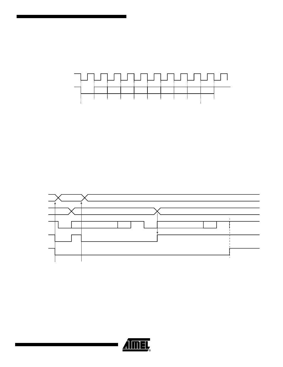
Figure 31-11. Transmitter Control
31.4.4
Peripheral Data Controller
Both the receiver and the transmitter of the Debug Unit's UART are generally connected to a
Peripheral Data Controller (PDC) channel.
The peripheral data controller channels are programmed via registers that are mapped within
the Debug Unit user interface from the offset 0x100. The status bits are reported in the Debug
Unit status register DBGU_SR and can generate an interrupt.
D0
D1
D2
D3
D4
D5
D6
D7
DTXD
Start
Bit
Parity
Bit
Stop
Bit
Example: Parity enabled
Baud Rate
Clock
DBGU_THR
Shift Register
DTXD
TXRDY
TXEMPTY
Data 0
Data 1
Data 0
Data 0
Data 1
Data 1
S
S
P
P
Write Data 0
in DBGU_THR
Write Data 1
in DBGU_THR
stop
stop