Rainbow Electronics AT91CAP9S250A User Manual
Page 90
90
6264A–CAP–21-May-07
AT91CAP9S500A/AT91CAP9S250A
15.3.4.3
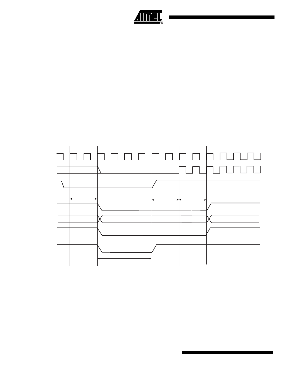
User Reset
The User Reset is entered when a low level is detected on the NRST pin and the bit URSTEN in
RSTC_MR is at 1. The NRST input signal is resynchronized with SLCK to insure proper behav-
ior of the system.
The User Reset is entered as soon as a low level is detected on NRST. The Processor Reset
and the Peripheral Reset are asserted.
The User Reset is left when NRST rises, after a two-cycle resynchronization time and a Y-cycle
processor startup. The processor clock is re-enabled as soon as NRST is confirmed high.
When the processor reset signal is released, the RSTTYP field of the Status Register
(RSTC_SR) is loaded with the value 0x4, indicating a User Reset.
T h e N R S T M a n a g e r g u a r a n t e e s t h a t t h e N R S T l i n e i s a s s e r t e d f o r
EXTERNAL_RESET_LENGTH Slow Clock cycles, as programmed in the field ERSTL. How-
ever, if NRST does not rise after EXTERNAL_RESET_LENGTH because it is driven low
externally, the internal reset lines remain asserted until NRST actually rises.
Figure 15-6. User Reset State
SLCK
periph_nreset
proc_nreset
NRST
NRST
(nrst_out)
>= EXTERNAL RESET LENGTH
MCK
Processor Startup
= 2 cycles
Any
Freq.
Resynch.
2 cycles
RSTTYP
Any
XXX
Resynch.
2 cycles
0x4 = User Reset