2 smc pulse register – Rainbow Electronics AT91CAP9S250A User Manual
Page 207
207
6264A–CAP–21-May-07
AT91CAP9S500A/AT91CAP9S250A
22.14.2
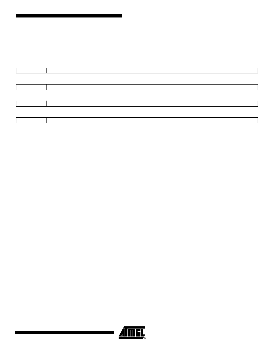
SMC Pulse Register
Register Name:
SMC_PULSE[0..
5
]
Access Type:
Read/Write
• NWE_PULSE: NWE Pulse Length
The NWE signal pulse length is defined as:
NWE pulse length = (256* NWE_PULSE[6] + NWE_PULSE[5:0]) clock cycles
The NWE pulse length must be at least 1 clock cycle.
• NCS_WR_PULSE: NCS Pulse Length in WRITE Access
In write access, the NCS signal pulse length is defined as:
NCS pulse length = (256* NCS_WR_PULSE[6] + NCS_WR_PULSE[5:0]) clock cycles
The NCS pulse length must be at least 1 clock cycle.
• NRD_PULSE: NRD Pulse Length
In standard read access, the NRD signal pulse length is defined in clock cycles as:
NRD pulse length = (256* NRD_PULSE[6] + NRD_PULSE[5:0]) clock cycles
The NRD pulse length must be at least 1 clock cycle.
In page mode read access, the NRD_PULSE parameter defines the duration of the subsequent accesses in the page.
• NCS_RD_PULSE: NCS Pulse Length in READ Access
In standard read access, the NCS signal pulse length is defined as:
NCS pulse length = (256* NCS_RD_PULSE[6] + NCS_RD_PULSE[5:0]) clock cycles
The NCS pulse length must be at least 1 clock cycle.
In page mode read access, the NCS_RD_PULSE parameter defines the duration of the first access to one page.
31
30
29
28
27
26
25
24
–
NCS_RD_PULSE
23
22
21
20
19
18
17
16
–
NRD_PULSE
15
14
13
12
11
10
9
8
–
NCS_WR_PULSE
7
6
5
4
3
2
1
0
–
NWE_PULSE