5 master receiver mode, Figure 34-6, Figure 34-7 – Rainbow Electronics AT91CAP9S250A User Manual
Page 488: Figure 34-8
488
6264A–CAP–21-May-07
AT91CAP9S500A/AT91CAP9S250A
TXRDY is used as Transmit Ready for the PDC transmit channel.
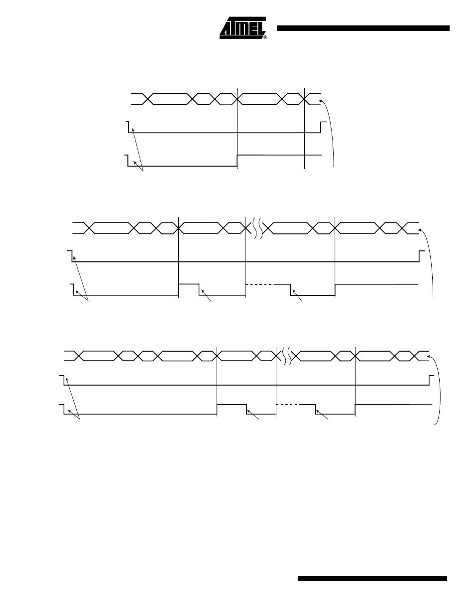
Figure 34-6. Master Write with One Data Byte
Figure 34-7. Master Write with Multiple Data Byte
Figure 34-8. Master Write with One Byte Internal Address and Multiple Data Bytes
34.7.5
Master Receiver Mode
The read sequence begins by setting the START bit. After the start condition has been sent, the
master sends a 7-bit slave address to notify the slave device. The bit following the slave address
indicates the transfer direction, 1 in this case (MREAD = 1 in TWI_MMR). During the acknowl-
edge clock pulse (9th pulse), the master releases the data line (HIGH), enabling the slave to pull
it down in order to generate the acknowledge. The master polls the data line during this clock
pulse and sets the NACK bit in the status register if the slave does not acknowledge the byte.
If an acknowledge is received, the master is then ready to receive data from the slave. After data
has been received, the master sends an acknowledge condition to notify the slave that the data
has been received except for the last data, after the stop condition. See
. When the
TXCOMP
TXRDY
Write THR (DATA)
STOP sent automaticaly
(ACK received and TXRDY = 1)
TWD
A
DATA
A
S
DADR
W
P
A
DATA n
A
S
DADR
W
DATA n+5
A
P
DATA n+x
A
TXCOMP
TXRDY
Write THR (Data n)
Write THR (Data n+1)
Write THR (Data n+x)
Last data sent
STOP sent automaticaly
(ACK received and TXRDY = 1)
TWD
A
IADR(7:0)
A
DATA n
A
S
DADR
W
DATA n+5
A
P
DATA n+x
A
TXCOMP
TXRDY
TWD
Write THR (Data n)
Write THR (Data n+1)
Write THR (Data n+x)
Last data sent
STOP sent automaticaly
(ACK received and TXRDY = 1)