Figure 34-12, Figure 34-11 – Rainbow Electronics AT91CAP9S250A User Manual
Page 490
490
6264A–CAP–21-May-07
AT91CAP9S500A/AT91CAP9S250A
The three internal address bytes are configurable through the Master Mode register
(TWI_MMR).
If the slave device supports only a 7-bit address, i.e. no internal address, IADRSZ must be set to
0.
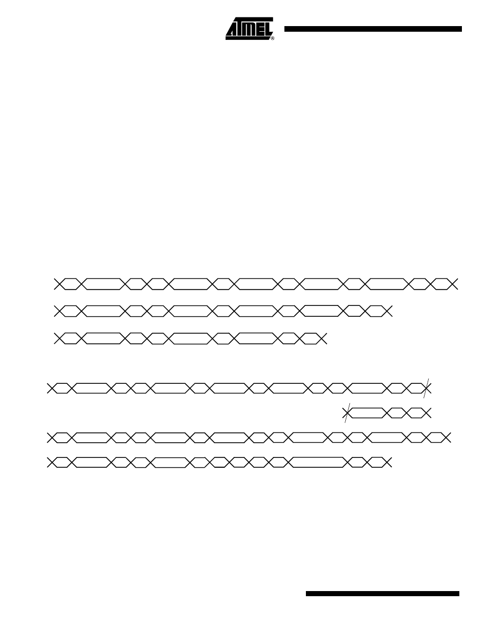
In the figures below the following abbreviations are used:
Figure 34-11. Master Write with One, Two or Three Bytes Internal Address and One Data Byte
Figure 34-12. Master Read with One, Two or Three Bytes Internal Address and One Data Byte
34.7.6.2
10-bit Slave Addressing
For a slave address higher than 7 bits, the user must configure the address size (IADRSZ) and
set the other slave address bits in the internal address register (TWI_IADR). The two remaining
Internal address bytes, IADR[15:8] and IADR[23:16] can be used the same as in 7-bit Slave
Addressing.
Table 34-4.
• S
Start
• P
Stop
• W
Write
• R
Read
• A
Acknowledge
• N
Not Acknowledge
• DADR
Device Address
• IADR
Internal Address
S
DADR
W
A
IADR(23:16)
A
IADR(15:8)
A
IADR(7:0)
A
DATA
A
P
S
DADR
W
A
IADR(15:8)
A
IADR(7:0)
A
P
DATA
A
A
IADR(7:0)
A
P
DATA
A
S
DADR
W
TWD
Three bytes internal address
Two bytes internal address
One byte internal address
TWD
TWD
S
DADR
W
A
IADR(23:16)
A
IADR(15:8)
A
IADR(7:0)
A
S
DADR
W
A
IADR(15:8)
A
IADR(7:0)
A
A
IADR(7:0)
A
S
DADR
W
DATA
N
P
S
DADR
R
A
S
DADR
R
A
DATA
N
P
S
DADR
R
A
DATA
N
P
TWD
TWD
TWD
Three bytes internal address
Two bytes internal address
One byte internal address