Rainbow Electronics AT91CAP9S250A User Manual
Page 467
467
6264A–CAP–21-May-07
AT91CAP9S500A/AT91CAP9S250A
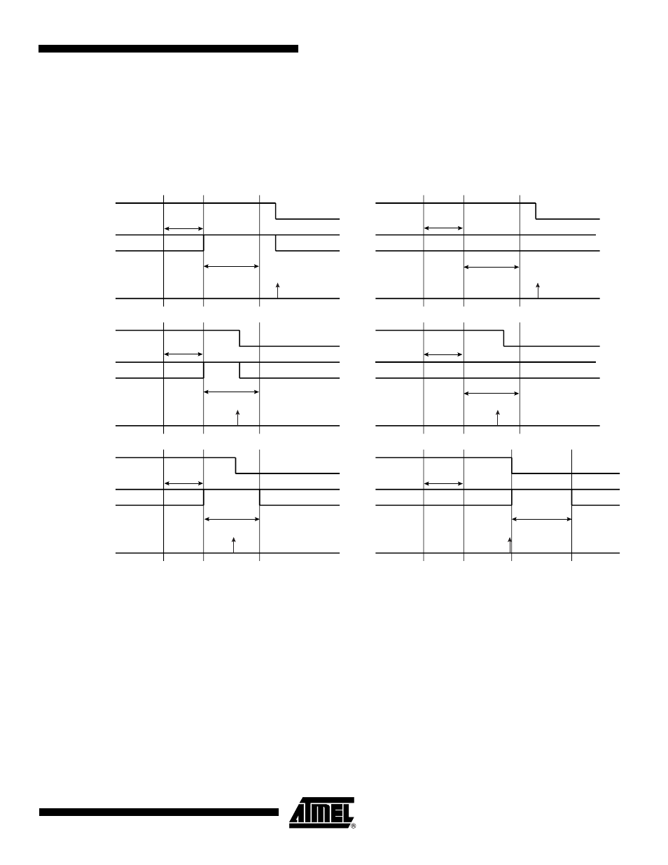
To facilitate interfacing with such devices, the Chip Select Register can be programmed with
the CSAAT bit (Chip Select Active After Transfer) at 1. This allows the chip select lines to
remain in their current state (low = active) until transfer to another peripheral is required.
shows different peripheral deselection cases and the effect of the CSAAT bit.
Figure 33-8. Peripheral Deselection
33.6.3.8
Mode Fault Detection
A mode fault is detected when the SPI is programmed in Master Mode and a low level is
driven by an external master on the NPCS0/NSS signal. NPCS0, MOSI, MISO and SPCK
must be configured in open drain through the PIO controller, so that external pull up resistors
are needed to guarantee high level.
When a mode fault is detected, the MODF bit in the SPI_SR is set until the SPI_SR is read
and the SPI is automatically disabled until re-enabled by writing the SPIEN bit in the SPI_CR
(Control Register) at 1.
By default, the Mode Fault detection circuitry is enabled. The user can disable Mode Fault
detection by setting the MODFDIS bit in the SPI Mode Register (SPI_MR).
A
NPCS[0..3]
Write SPI_TDR
TDRE
NPCS[0..3]
Write SPI_TDR
TDRE
NPCS[0..3]
Write SPI_TDR
TDRE
DLYBCS
PCS = A
DLYBCS
DLYBCT
A
PCS = B
B
DLYBCS
PCS = A
DLYBCS
DLYBCT
A
PCS = B
B
DLYBCS
DLYBCT
PCS=A
A
DLYBCS
DLYBCT
A
PCS = A
A
A
DLYBCT
A
A
CSAAT = 0
DLYBCT
A
A
CSAAT = 1
A