4 ddrsdrc timing 0 parameter register, Section – Rainbow Electronics AT91CAP9S250A User Manual
Page 237
237
6264A–CAP–21-May-07
AT91CAP9S500A/AT91CAP9S250A
23.6.4
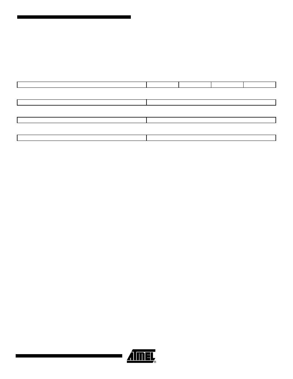
DDRSDRC Timing 0 Parameter Register
Register Name:
DDRSDRC_T0PR
Access Type:
Read/Write
Reset Value:
See
• TRAS: Active to precharge delay
Reset Value is 5 cycles.
This field defines the delay between an Activate Command and a Precharge Command in number of cycles. Number of
cycles is between 0 and 15.
• TRCD: Row to column delay
Reset Value is 2 cycles.
This field defines the delay between an Activate Command and a Read/Write Command in number of cycles. Number of
cycles is between 0 and 15.
• TWR: Write recovery delay
Reset value is 2.
This field defines the Write Recovery Time in number of cycles. Number of cycles is between 1 and 15.
• TRC: Row cycle delay
Reset value is 7 cycles.
This field defines the delay between an Activate command and Refresh command in number of cycles. Number of cycles is
between 0 and 15
• TRP: Row precharge delay
Reset Value is 2 cycles.
This field defines the delay between a Precharge Command and another command in number of cycles. Number of cycles
is between 0 and 15.
• TRRD Active bankA to Active bankB
Reset value is 2.
This field defines the delay between an Active command in BankA and an active command in bankB in number of cycles.
Number of cycles is between 1 and 15.
31
30
29
28
27
26
25
24
TMRD
–
–
–
twtr
23
22
21
20
19
18
17
16
TRRD
TRP
15
14
13
12
11
10
9
8
TRC
TWR
7
6
5
4
3
2
1
0
TRCD
TRAS