8 loop mode, 9 interrupt – Rainbow Electronics AT91CAP9S250A User Manual
Page 591
591
6264A–CAP–21-May-07
AT91CAP9S500A/AT91CAP9S250A
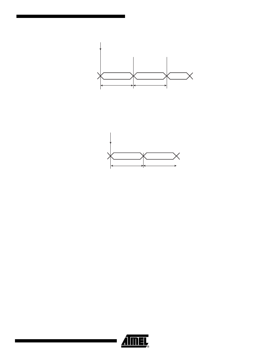
Figure 36-14. Transmit Frame Format in Continuous Mode
Note:
1. STTDLY is set to 0. In this example, SSC_THR is loaded twice. FSDEN value has no effect on
the transmission. SyncData cannot be output in continuous mode.
Figure 36-15. Receive Frame Format in Continuous Mode
Note:
1. STTDLY is set to 0.
36.6.8
Loop Mode
The receiver can be programmed to receive transmissions from the transmitter. This is done by
setting the Loop Mode (LOOP) bit in SSC_RFMR. In this case, RD is connected to TD, RF is
connected to TF and RK is connected to TK.
36.6.9
Interrupt
Most bits in SSC_SR have a corresponding bit in interrupt management registers.
The SSC can be programmed to generate an interrupt when it detects an event. The interrupt is
controlled by writing SSC_IER (Interrupt Enable Register) and SSC_IDR (Interrupt Disable Reg-
ister) These registers enable and disable, respectively, the corresponding interrupt by setting
and clearing the corresponding bit in SSC_IMR (Interrupt Mask Register), which controls the
generation of interrupts by asserting the SSC interrupt line connected to the AIC.
DATLEN
Data
DATLEN
Data
Default
Start
From SSC_THR
From SSC_THR
TD
Start: 1. TXEMPTY set to 1
2. Write into the SSC_THR
Data
DATLEN
Data
DATLEN
Start = Enable Receiver
To SSC_RHR
To SSC_RHR
RD