Rainbow Electronics AT91CAP9S250A User Manual
Page 300
300
6264A–CAP–21-May-07
AT91CAP9S500A/AT91CAP9S250A
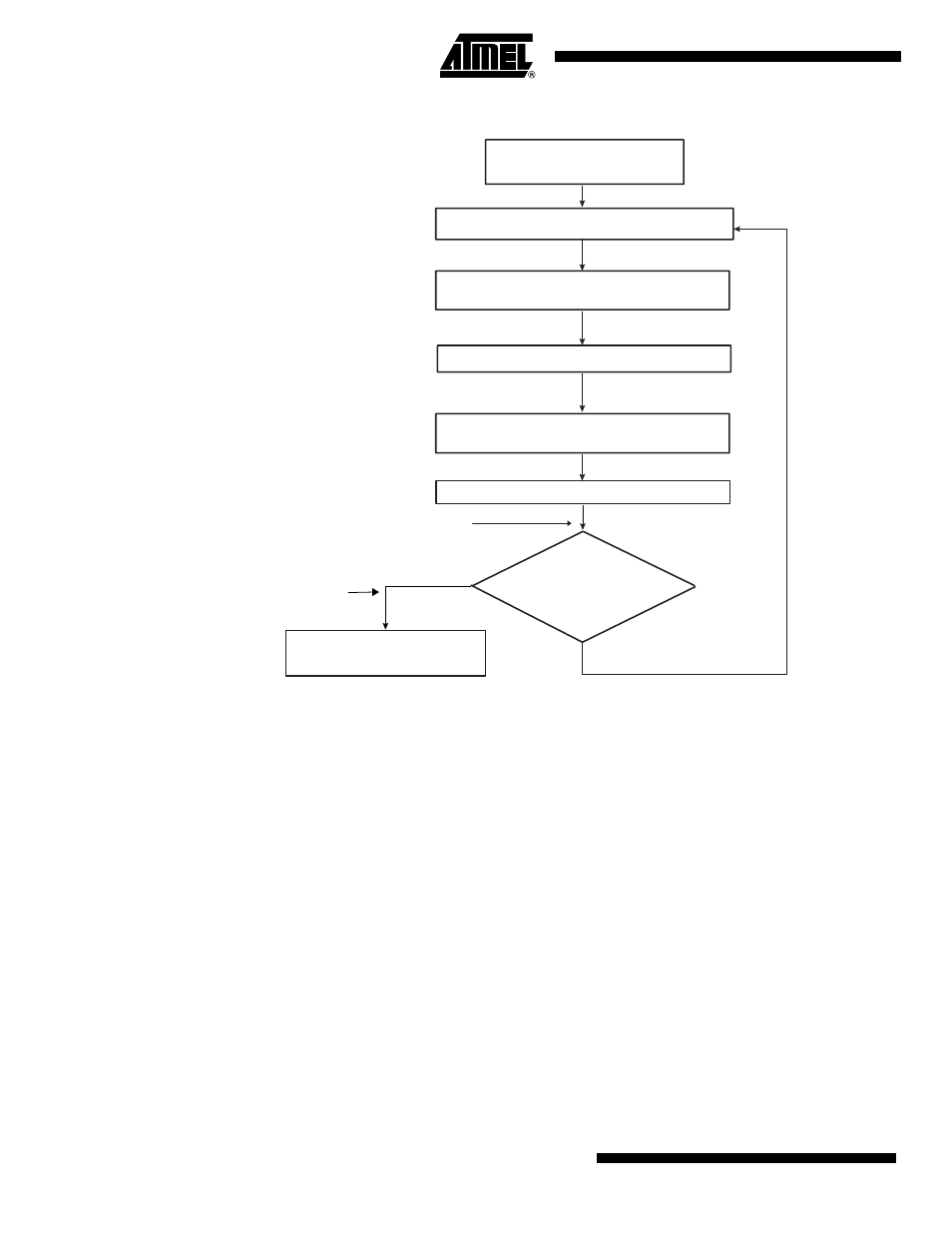
Figure 26-13. DMAC Transfer Flow for Replay Mode at Source and Linked List Destination Address
26.3.5.6
Multi-buffer Transfer with Source Address Auto-reloaded and Contiguous Destination Address (Row 11)
1.
Read the Channel Enable register to choose a free (disabled) channel.
2.
Clear any pending interrupts on the channel from the previous DMAC transfer by read-
ing to the Interrupt Status Register.
3.
Program the following channel registers:
a.
Write the starting source address in the DMAC_SADDRx register for channel x.
b.
Write the starting destination address in the DMAC_DADDRx register for channel
x.
c.
Program DMAC_CTRLAx, DMAC_CTRLBx and DMAC_CFGx according to Row
11 as shown in
. Program the DMAC_DSCRx register with
‘0’. DMAC_CTRLBx.AUTO field is set to ‘1’ to enable automatic mode support.
d.
Write the control information for the DMAC transfer in the DMAC_CTRLBx and
DMAC_CTRLAx register for channel x. For example, in this register, you can pro-
gram the following:
– i. Set up the transfer type (memory or non-memory peripheral for source and
destination) and flow control device by programming the FC of the DMAC_CTRLBx
register.
Channel Enabled by
software
LLI Fetch
yes
no
Hardware reprograms
DADDRx, CTRLAx, CTRLBx, DSCRx
DMA buffer transfer
Writeback of control
status information in LLI
Reload SADDRx
Buffer Complete interrupt
generated here
HDMA Transfer Complete
interrupt generated here
Channel Disabled by
hardware
Is HDMA in
Row1 of
HDMA State Machine Table?