10 pmc clock generator pll a register – Rainbow Electronics AT91CAP9S250A User Manual
Page 374
374
6264A–CAP–21-May-07
AT91CAP9S500A/AT91CAP9S250A
29.9.10
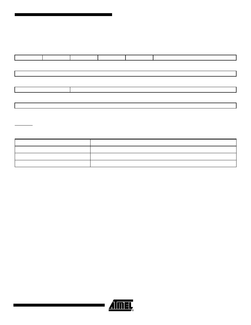
PMC Clock Generator PLL A Register
Register Name:
CKGR_PLLAR
Access Type:
Read/Write
Possible limitations on PLL A input frequencies and multiplier factors should be checked before using the PMC.
Warning: Bit 29 must always be set to 1 when programming the CKGR_PLLAR register.
• DIVA: Divider A
• PLLACOUNT: PLL A Counter
Specifies the number of Slow Clock cycles before the LOCKA bit is set in PMC_SR after CKGR_PLLAR is written.
• OUTA: PLL A Clock Frequency Range
To optimize clock performance, this field must be programmed as specified in “PLL Characteristics” in the Electrical Char-
acteristics section of the product datasheet.
• MULA: PLL A Multiplier
0 = The PLL A is deactivated.
1 up to 2047 = The PLL A Clock frequency is the PLL A input frequency multiplied by MULA + 1.
31
30
29
28
27
26
25
24
–
–
1
–
–
MULA
23
22
21
20
19
18
17
16
MULA
15
14
13
12
11
10
9
8
OUTA
PLLACOUNT
7
6
5
4
3
2
1
0
DIVA
DIVA
Divider Selected
0
Divider output is 0
1
Divider is bypassed
2 - 255
Divider output is the Main Clock divided by DIVA.