Table 2.7 parallel rom support, Parallel rom support – Avago Technologies LSI53C1000R User Manual
Page 89
Parallel ROM Interface
2-59
Version 2.2
Copyright © 2000–2003 by LSI Logic Corporation. All rights reserved.
The LSI53C1000R supports a variety of sizes and speeds of expansion
ROM. An example set of interface drawings is in
Appendix B, “External Memory Interface Diagram Examples.”
The
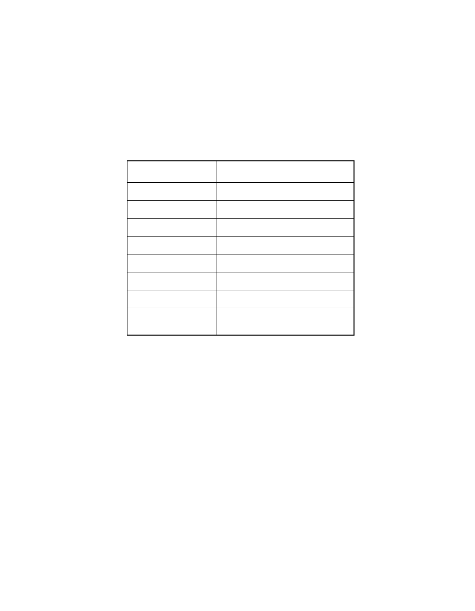
encoding of pins MAD[3:1] allows the user to define how much external
memory is available to the LSI53C1000R.
shows the memory
space associated with the possible values of MAD[3:1]. The MAD[3:1]
pins are fully described in
Chapter 3, “Signal Descriptions.”
To use one of the configurations mentioned above in a host adapter
board design, put 4.7 k
Ω
pull-up resistors on the MAD pins
corresponding to the available memory space. Each MAD pin has an
internal static pull-down; therefore, no external pull-down resistors are
needed. For example, to connect to a 64 Kbyte external ROM, use a
pull-up on MAD[2]. If the external memory interface is not used,
MAD[3:1] should be pulled HIGH.
The LSI53C1000R allows the system to determine the size of the
available external memory using the Expansion ROM Base Address
register in the PCI configuration space. For more information on how this
works, refer to the PCI specification or the Expansion ROM Base
Address register description in
MAD[0] is the slow ROM pin. When pulled up, it enables two extra clock
cycles of data access time to allow use of slower memory devices. The
external memory interface also supports updates to flash memory.
Table 2.7
Parallel ROM Support
MAD[3:1]
Available Memory Space
000
16 Kbytes
001
32 Kbytes
010
64 Kbytes
011
128 Kbytes
100
256 Kbytes
101
512 Kbytes
110
1024 Kbytes
111
No external memory present,
ROM interface disabled