4 read/write instructions, 1 first dword, Figure5.7 read/write instruction – first dword – Avago Technologies LSI53C1000R User Manual
Page 265: Read/write instructions, First dword, Read/write instruction – first dword, Section 5.4, “read/write instructions
Read/Write Instructions
5-23
Version 2.2
Copyright © 2000–2003 by LSI Logic Corporation. All rights reserved.
5.4 Read/Write Instructions
The Read/Write instruction supports addition, subtraction, and comparison
of two separate values within the chip. It performs the desired operation
on the specified register and the
SCSI First Byte Received (SFBR)
register
and stores the result back to the specified register or to the SFBR. If the
COM bit (
, bit 0) is cleared, Read/Write instructions
cannot be used.
5.4.1 First Dword
This section describes the first Dword of the Read/Write Instruction
register.
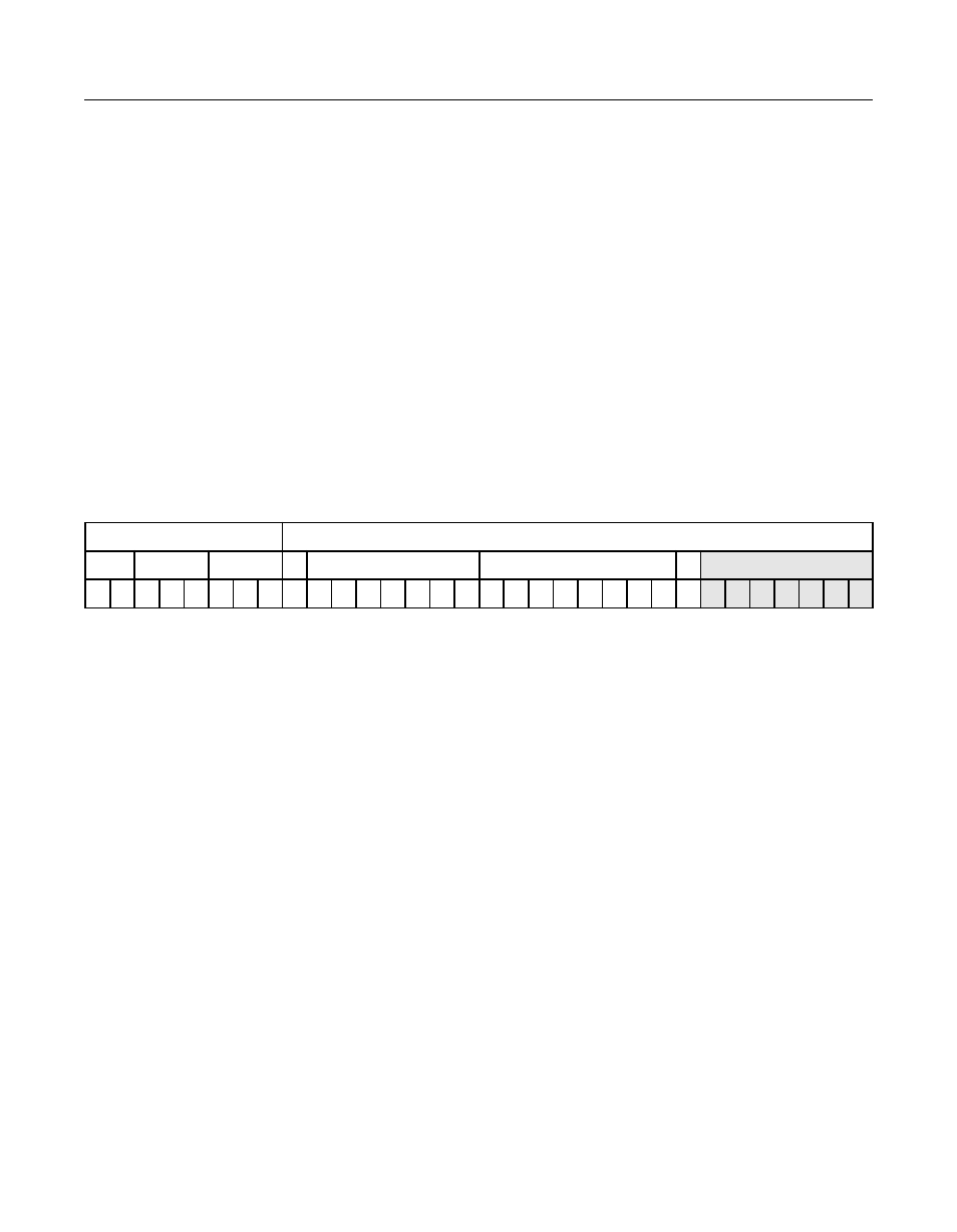
Figure 5.7
Read/Write Instruction – First Dword
IT[1:0]
Instruction Type – Read/Write Instruction
[31:30]
The Read/Write instruction uses operator bits [26:24] in
conjunction with the opcode bits to determine which
instruction is currently selected.
OPC[2:0]
Opcode
[29:27]
These bits determine if the instruction is a Read/Write or
an I/O instruction. Opcodes 0b000 through 0b100 are
considered I/O instructions.
O[2:0]
Operator
[26:24]
The Operator bits are used in conjunction with the
opcode bits to determine which instruction is currently
selected. Refer to
on
for field
definitions.
D8
Use data8/SFBR
23
When this bit is set,
SCSI First Byte Received (SFBR)
is
used, instead of the data8 value, during a
Read-Modify-Write instruction (refer to
). This
allows the user to add two register values.
31 30 29
27 26
24 23 22
16 15
8
7
6
0
DCMD Register
DBC Register
IT[1:0] OPC[2:0]
O[2:0]
D8 Register Address [6:0]
Immediate Data
A7
R
0
1
x
x
x
x
x
x
x
x
x
x
x
x
x
x
x
x
x
x
x
x
x
x
0
0
0
0
0
0
0
0