Table 2.6 scf divisor values, Scf divisor values – Avago Technologies LSI53C1000R User Manual
Page 72
2-42
Functional Description
Version 2.2
Copyright © 2000–2003 by LSI Logic Corporation. All rights reserved.
2.2.15.1
Register, Bits [6:4] (SCF[2:0]) Description
The SCF[2:0] bits select the factor by which the frequency of SCLK is
divided before its presentation to the synchronous SCSI control logic.
The synchronous transfer speed is determined by the combination of the
divided clock and the setting of the XCLKS_ST, XCLKS_DT, XCLKH_ST,
and XCLKH_DT bits in the
register.
provides the clock dividers available. Refer to
, “
," and
Single Transition Transfer Rates,"
located in the
register description, for a full list of available
synchronous transfer rates.
2.2.15.2
Register, Bits [3:0] Description
The following extra clock bits add an extra clock of setup or hold to a ST
or DT transaction.
Bit 3, XCLKH_DT (Extra Clock of Data Hold on DT transfer edge), adds
a clock of data hold to synchronous DT SCSI transfers on the DT edge.
This bit only impacts DT transfers as it only affects data hold to the DT
edge. Setting this bit reduces the synchronous transfer send rate but
does not reduce the rate at which the LSI53C1000R receives outbound
REQs, ACKs, or data.
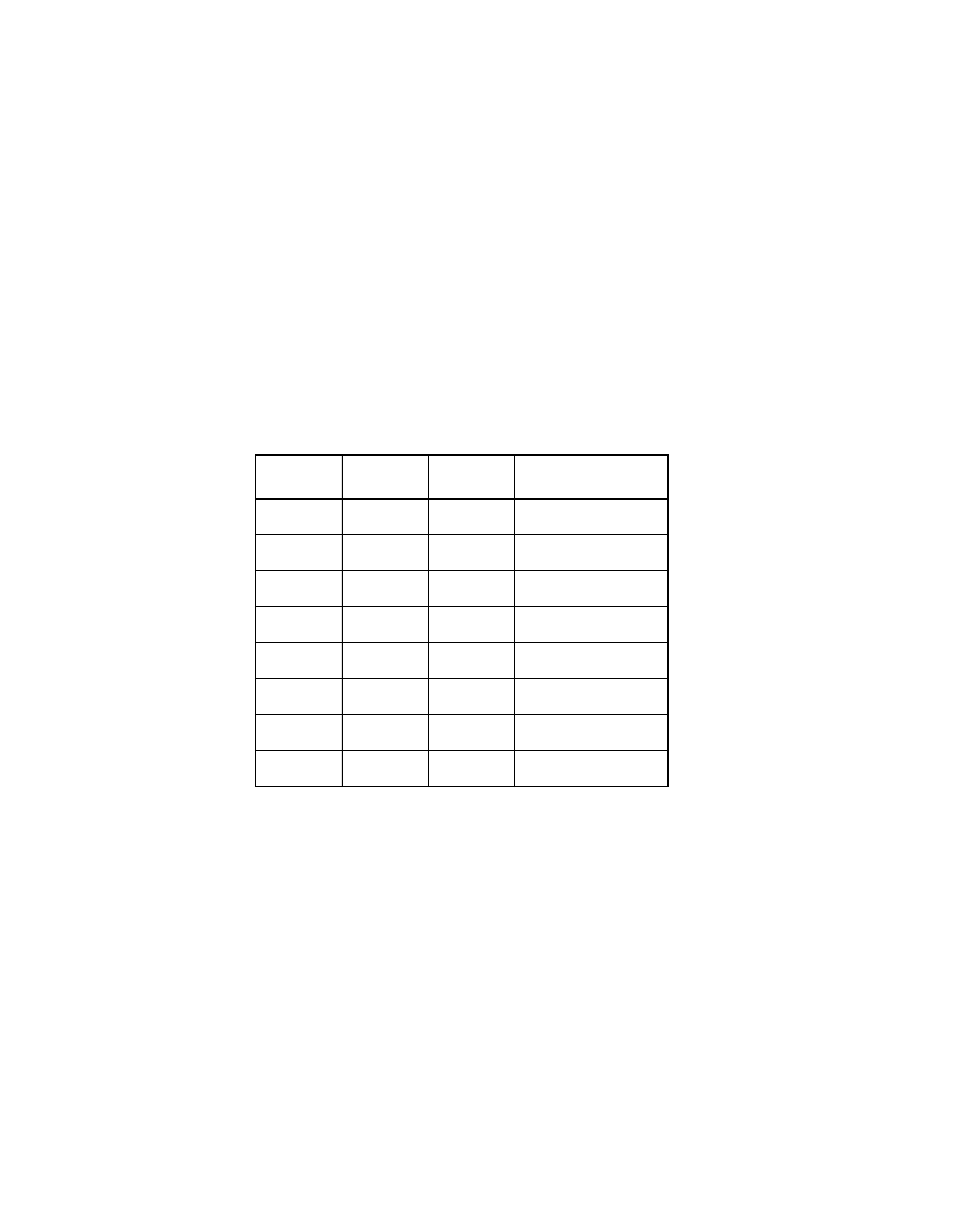
Table 2.6
SCF Divisor Values
SCF2
SCF1
SCF0
SCLK Divisor
0
0
0
SCLK/3
0
0
1
SCLK/1
0
1
0
SCLK/1.5
0
1
1
SCLK/2
1
0
0
SCLK/3
1
0
1
SCLK/4
1
1
0
SCLK/6
1
1
1
SCLK/8