Rockwell Automation 1747-PT1, D1747NP002 Hand-Held Terminal User Manual
Page 94
Chapter 5
Ladder Program Basics
5–10
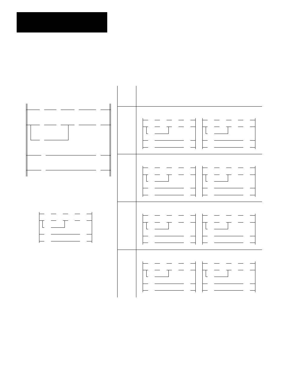
When the state of a bit changes during the scan, the effects this may have in
earlier rungs of the program are not accounted for until the next scan. To
point this out, we have shown successive scans (1000 and 1001, 2000 and
2001, etc.).
The diagram above is the same one that appears on the
preceding page. This diagram is also represented below,
with each instruction replaced with a T or F, indicating
the initial True/False status of the instruction.
The table at the right indicates how the instructions are
executed when XIC instruction I:0/1 changes state.
(I:0/1 represents an external momentary contact push
button.)
T
T
F
F
T
T
T
T
F
T
T
T
T
T
F
T
F
T
F
T
T
T
T
T
T
T
F
T
F
F
F
T
T
F
F
F
F
F
F
Instruction Execution
T = true at time of execution
F = false at time of execution
XIC
I:0/1
Goes
True
Goes
False
Scan 1000
Scan 1001
F
F
T
F
F
F
T
T
T
F
F
T
T
F
T
T
F
F
T
T
T
T
F
F
T
T
Scan 2000
Scan 2001
T
T
T
T
T
T
F
F
T
T
T
F
F
T
F
F
F
T
F
T
F
F
T
T
F
F
Scan 3000
Scan 3001
F
F
F
F
F
F
T
F
F
F
F
F
F
F
T
F
F
F
T
T
F
F
F
F
F
F
Scan 4000
Scan 4001
Goes
False
Goes
True
]/[
B3
10
1
] [
I:0.0
1
( )
B3
11
( )
B3
12
2
] [
B3
11
]/[
B3
12
]/[
B3
10
( )
2
( )
B3
10
] [
I:0.0
1
] [
B3
11
3
4
] [
B3
11
] [
I:0.0
1
O:0.0
- 20P PowerFlex DC Drive - Frame D Bimetal Thermostat (10 pages)
- 1336S_F_T_E_R F Frame Snubber Resistor Repl. (6 pages)
- 22-COMM PowerFlex 4-Class DSI (Drive Serial Interface) Network Communication Adapter (4 pages)
- 8-545 Plug In Solid State Relay (2 pages)
- 20-HIM-B1 PowerFlex 7-Class HIM Bezel (DPI) (4 pages)
- 100 Contactors with DC Coil (1 page)
- 100 Contactors with DC Coil (2 pages)
- 20P PowerFlex DC Drive - Frame D Switching Power Supply Circuit Board (6 pages)
- 140G-MTFx_MTHx_MTIx_MTKx Trip Unit Installation-140G-M (6 pages)
- 45BRD Analog Laser Sensor (4 pages)
- 20D Multi-Device Interface Option Board for PowerFlex 700S Drives (20 pages)
- 56RF RFID 18 mm Cylindrical Transceiver (2 pages)
- 42KC Miniature Rectangular: 5V DC Version (2 pages)
- 20P PowerFlex DC Drive - Frame A Switching Power Supply Circuit Board (16 pages)
- 21P-MISC-A-TP-2 Transition Tube Kit #C19-6/7 For PowerFlex 755 w/OEM Liquid Cooling Fr 6/7 Drive (2 pages)
- 42BT Background Suppression Sensor (3 pages)
- 42CB High Speed 18mm Cylindrical (4 pages)
- 140EX-JE2_JE3 Molded Case Circuit Breaker (4 pages)
- 140G-K-EAM1A Early Make Aux Contact for Rotary Handle Oper Mech-140G-K (1 page)
- 140G-K-EAM1A Early Make Aux Contact for Rotary Handle Oper Mech-140G-K (3 pages)
- 20-HIM-A6 PowerFlex (Human Interface Module) (74 pages)
- 42CF General Purpose 12mm Cylindrical (4 pages)
- 20D PowerFlex 700S Phase II Drive Frames 1...6 (80 pages)
- 140EX-HE1_HE2 Molded Case Circuit Breaker (6 pages)
- 140EX-HE1_HE2 Molded Case Circuit Breaker (4 pages)
- 20B PowerFlex 700 Custom Firmware - Pump Off (12 pages)
- 20-WIM-N4S DPI Wireless Interface Module (92 pages)
- 140U H-Frame Circuit Breaker Fixed and Adjustable Thermal Trip (7 pages)
- 140U H-Frame Circuit Breaker Fixed and Adjustable Thermal Trip (2 pages)
- 60-2619, 42JS Swivel/Tilt Mounting Bracket (1 page)
- 22A PowerFlex 4/40/400 Flange Mount (4 pages)
- 45MLA Controller Installation Instructions (16 pages)
- 20P PowerFlex DC Drive - Cooling Fan for Frame A Drives Above 73A at 230V 460V AC (6 pages)
- 42JS Series 7000 to 42JS VisiSight Replacement Kit (2 pages)
- 22A PowerFlex 4-Class HIM Bezel (DSI) (4 pages)
- 42CS Stainless Steel Photoelectric Sensors (4 pages)
- 20L-LL PowerFlex 700L Liquid-to-Liquid Heat Exchanger (40 pages)
- 20P PowerFlex DC Drive - Frame B SCR Modules (20 pages)
- 22B PowerFlex 40 Quick Start FRN 5.xx - 6.xx (161 pages)
- 22B PowerFlex 40 Quick Start FRN 5.xx - 6.xx (22 pages)
- 22F PowerFlex 4M Input RFI Filters (2 pages)
- 45LFM Capacitive Label Sensor (4 pages)
- 140G-Rx Installation Instruction-140G-R (2 pages)
- 140G-Rx Installation Instruction-140G-R (29 pages)
- 22C PowerFlex 400 AC Drive Quick Start - FRN 1-4.xx (28 pages)