Control block layout – Rockwell Automation 1747-PT1, D1747NP002 Hand-Held Terminal User Manual
Page 253
Instructions
Chapter 18
I/O Message and Communication
18–7
Control Block Layout
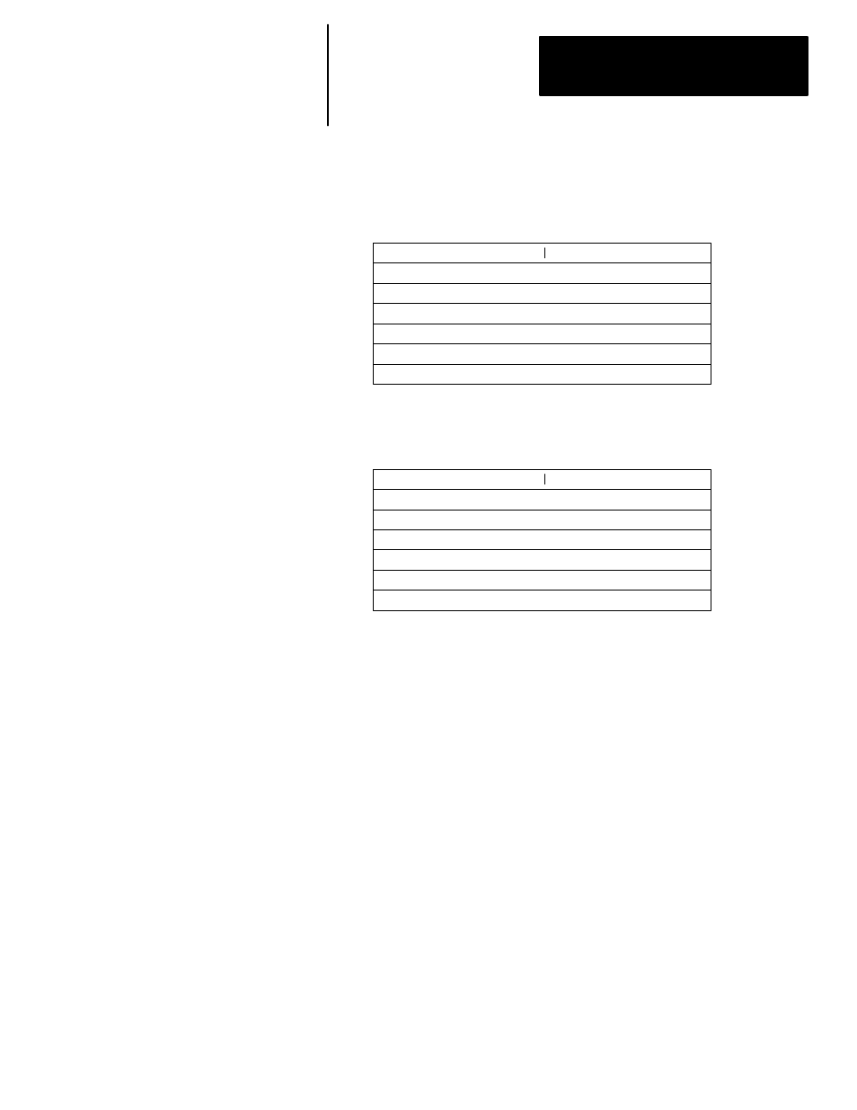
The control block layout if you select 500 CPU as the target device:
EN ST DN ER EW NR TO Error Code
15 14 13 12 11 10 09 08 07 06 05 04 03 02 01 00
Target Device Node Number
Reserved for message length in words
Control Block Layout – 500 CPU
Word
0
1
2
Target Address File Number
Target File Type (S, B, T, C, R, N) Code
Target Address Element Number
Reserved
3
4
5
6
The control block layout if you select 485 CIF as the target device:
EN ST DN ER EW NR TO Error Code
15 14 13 12 11 10 09 08 07 06 05 04 03 02 01 00
Target Device Node Number
Reserved for message length in words
Control Block Layout – 485 CIF
Word
0
1
2
Target Device Offset
Not used
Not used
Not used
3
4
5
6
MSG Instruction Status Bits
The upper byte of the first word in the control block contains the MSG
instruction status bits.
•
Bit 15, EN – Enable bit. This bit is set when rung conditions go true and
the instruction is being executed. It remains set until message
transmission is completed and the rung goes false.
•
Bit 14, ST – Start bit. This bit is set when the processor receives
acknowledgement from the target device. The ST bit is reset when the
DN bit or ER bit is set.
•
Bit 13, DN – Done bit. This bit is set when the message is transmitted
successfully and is replied to by the target device. The DN bit is reset the
next time the associated rung goes from false–to–true.
•
Bit 12, ER – Error bit. This bit is set when message transmission has
failed. The ER bit is reset the next time the associated rung goes from
false–to–true.
•
Bit 10, EW – Enabled and waiting. This bit is set after the enable bit is
set and the message is waiting to be sent.
•
Bit 09, NR – No response bit. This bit is set if the target processor does
not acknowledge the message request. The NR bit is reset when the ER
bit or DN bit is set.
•
Bit 08, TO – Time out bit. You can set this bit in your application to
remove an active message instruction from processor control. Your
application must supply its own timeout value. An example appears on
page 18–13.