A 1–rung ladder program – Rockwell Automation 1747-PT1, D1747NP002 Hand-Held Terminal User Manual
Page 86
Chapter 5
Ladder Program Basics
5–2
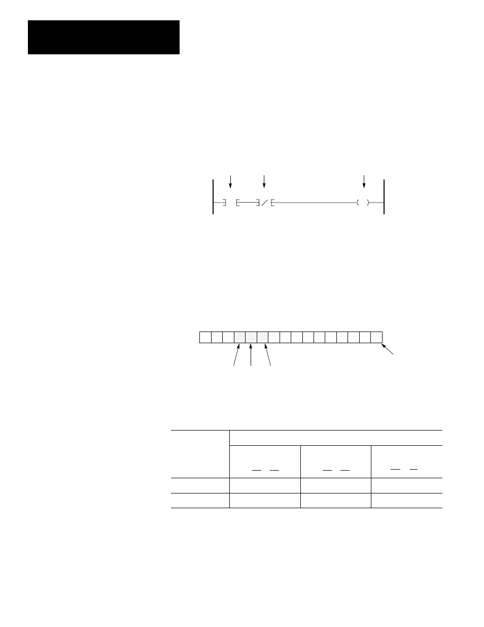
A ladder program consists of individual rungs, each containing at least one
output instruction and one or more input instructions. Variations of this
simple rung construction are discussed in later chapters.
This ladder rung has two input instructions and an output instruction. An
output instruction always appears at the right, next to the right power rail.
Input instructions always appear to the left of the output instruction.
XIC = Examine if Closed
XIO = Examine if Open
OTE = Output energize
Address B3/10
Address B3/11
Address B3/12
A Simple Rung, Using Relay Logic Instructions
B3
10
B3
11
XIC
XIO
OTE
Input Instructions
Output Instructions
B3
12
Note that each instruction in the diagram above has an address. As described
in the chapter 4, this address identifies a location in the processor’s data files,
where the on/off state of the bit is stored. Addresses of the above
instructions indicate they are located in the Bit data file (B3), bits 10, 11, and
12:
OTE
XIC
XIO
Bit Data File 3
– Element 0
Bit Status
0 0 0 1 0 1 0 0 0 0 0 0 0 0 0 0
15 14 13 12 11 10 9 8 7 6 5 4 3 2 1 0
In the preceding diagram, we indicated that bit 10 is logic 1 (on), bit 11 is
logic 0 (off), and bit 12 is logic 1 (on). These logic states indicate whether
an instruction is true or false, as pointed out in the table below.
The status of the instruction is
If the data table bit
is
XIC
Examine if Closed
] [
XIO
Examine if Open
]/[
OTE
Output Energize
( )
Logic 0
False
True
False
Logic 1
True
False
True
From the diagram and table above, we see that the state of bits 10, 11, and 12
indicate that the XIC, XIO, and OTE instructions of our rung are all true.
The true/false state of instructions is the basis of controller operation, as
indicated in the following paragraphs.
A 1–Rung Ladder Program