The pid concept – Rockwell Automation 1747-PT1, D1747NP002 Hand-Held Terminal User Manual
Page 347
Chapter 26
PID Instruction
26–3
The PID instruction normally controls a closed loop using inputs from an
analog input module and providing an output to an analog output module.
For temperature control, you can convert the analog output to a time
proportioning on/off output for driving a heater or cooling unit. An example
appears on pages 26–20 and 26–22.
The PID instruction can be operated in the timed mode or the STI mode. In
the timed mode, the instruction updates its output periodically at the rate you
set. In the STI mode, the instruction should be placed in an STI interrupt
subroutine. It will then update its output every time the STI subroutine is
scanned. The STI time interval and the PID loop update rate must be the
same in order for the equation to execute properly.
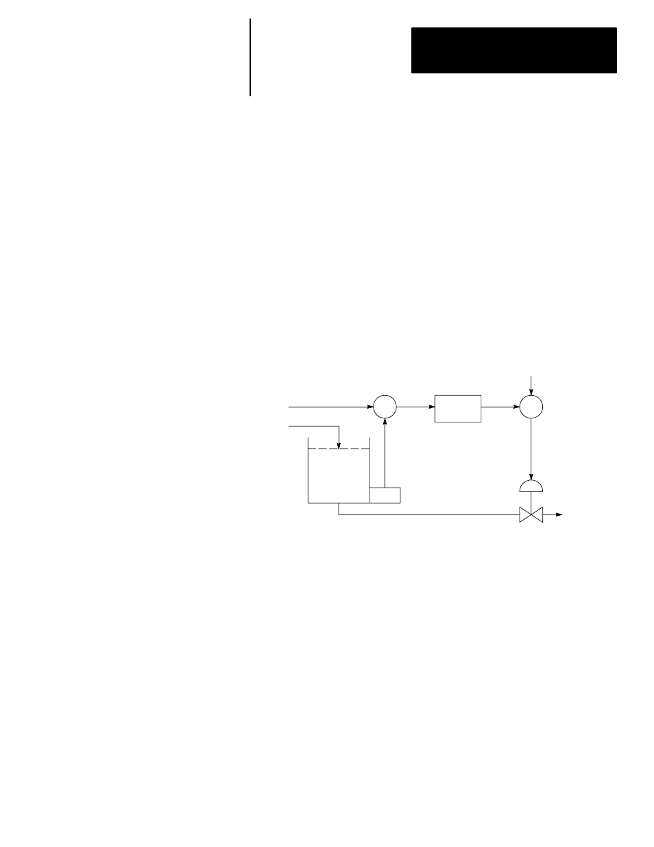
PID closed loop control holds a process variable at a desired set point. A
flow rate/fluid level example is shown below.
∑
∑
PID
Equation
FFWD
or Bias
Control
Output
Level
Detector
Process
Variable
Error
Set Point
Flow Rate
Control Valve
The PID equation controls the process by sending an output signal to the
control valve. The greater the error between the setpoint and process
variable input, the greater the output signal, and vice versa. An additional
value (feedforward or bias) can be added to the control output as an offset.
The result of PID calculation (control variable) will drive the process
variable you are controlling toward the set point.
The PID Concept