Bit data file (b3), Timer data file (t4), Counter data file (c5) – Rockwell Automation 1747-PT1, D1747NP002 Hand-Held Terminal User Manual
Page 194: Next_fl
Chapter 12
Monitoring Controller Operations
12–8
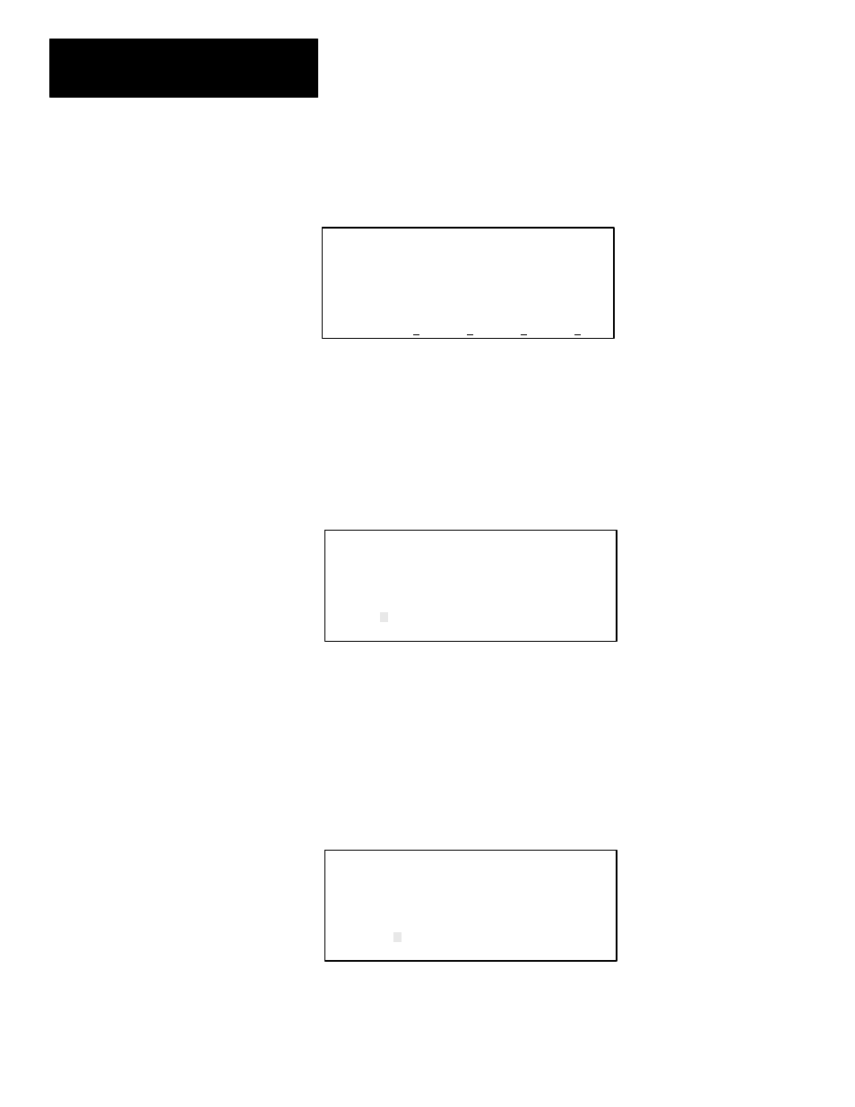
Bit Data File (B3)
The display below shows the bit data file. Two elements are shown; B3:0
and B3:1. The cursor is located on bit B3/0. All bits are reset to zero.
ADDRESS NEXT FL PREV FL NEXT PG PREV PG
F1
F2
F3
F4
F5
Address 15 data 0
B3:0 0000 0000 0000 0000
B3:1 0000 0000 0000 0000
B3/0 = 0 RUN
To display the next consecutive data file – the timer data file, press [
F2
],
NEXT_FL.
Timer Data File (T4)
The display below shows the timer data file. The cursor is on the enable bit
(EN) of timer T4:0. The control words EN, TT, and DN (bits 15, 14, and 13)
are all reset. The preset is currently 1000 and the accumulator is 0.
F1
F2
F3
F4
F5
NEXT_PG PREV_PG
ADDRESS NEXT_FL PREV_FL
Timer
T4:0
EN
TT
DN
STATUS
0
0
0
PRESET
1000
ACCUM
0
STATUS=000
RUN
To display the next consecutive data file – the counter data file, press [
F2
],
NEXT_FL.
Counter Data File (C5)
The display below shows the counter data file. The cursor is on the count–up
enable bit CU (bit 15) of counter C5:0. The control word bits CU, CD, DN,
OV, UN, and UA (bits 15, 14, 13, 12, 11, and 10 respectively) are all reset.
The preset is currently 10 and the accumulator is 0.
F1
F2
F3
F4
F5
NEXT_PG PREV_PG
ADDRESS NEXT_FL PREV_FL
Counter
C5:0
CU
CD
DN
OV
UN
UA
STATUS
0
0
0
0
0
0
PRESET
10
ACCUM
0
STATUS=000000
RUN
To display the next consecutive data file – the control data file, press [
F2
],
NEXT_FL.