Rockwell Automation 1747-PT1, D1747NP002 Hand-Held Terminal User Manual
Page 473
Appendix D
Estimating Scan Time
D–7
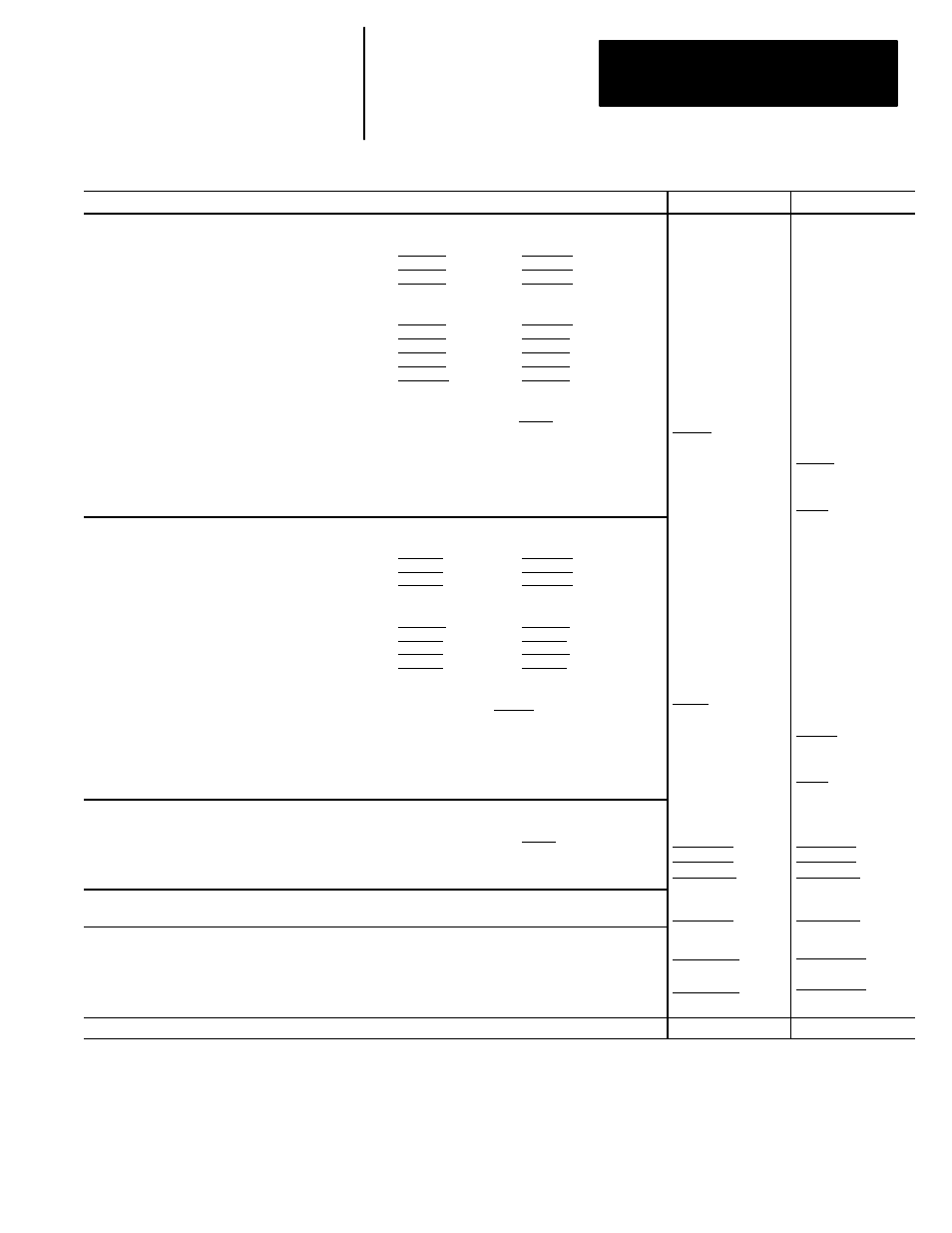
Example: Worksheet B – Estimating the Scan Time of a 1747–L514 Processor Application
Procedure:
Min Scan Time:
Max ScanTime:
1. Estimate your input scan time (
µ
s).
A. Calculate the processor input scan of your discrete input modules.
Number of 8 point modules
2 x 197 =
a.) 394
Number of 16 point modules
1 x 313 =
b.) 313
Number of 32 point modules
0 x 545 =
c.) 0
B. Calculate the processor input scan of your specialty I/O modules.
Number of 1/4 DCM or analog combo
1 x 652 =
d.) 652
Number of 1/2 DCM, analog input, or 1746–HS
0 x 1126 =
e.) 0
Number of 3/4 DCM
0 x 1600=
f.) 0
Number of full DCM, BASIC, or 1747–DSN
0 x 2076=
g.) 0
Number of 1747–KE
0 x 443 =
h.) 0
C. Add lines a through h. Place this value on line (i).
Add 101 to the value on line (i). This sum is your minimum input scan time.
i.) 1359 + 101 =
D. Calculate your maximum input scan time:
Maximum input scan time = Minimum scan time + (Number of specialty I/O modules x 50)
E. Calculate the Forced Input Overhead: Forced Input Overhead =
(Number of input modules x 180) + 140 per additional word for multi–word modules (e.g. DCM, analog, DSN)
1460
1510
860
2. Estimate your output scan time (
µ
s).
A. Calculate the processor output scan of your discrete output modules.
Number of 8 point modules
1 x 173 =
a.) 173
Number of 16 point modules
0 x 272 =
b.) 816
Number of 32 point modules
0 x 470
=
c.) 0
B. Calculate the processor output scan of your specialty I/O modules.
Number of 1/4 DCM or analog combo
1 x 620 =
d.) 620
Number of 1/2 DCM, analog output, or 1746–HS
0 x 1028 =
e.) 0
Number of 3/4 DCM
0 x 1436 =
f.) 0
Number of full DCM, BASIC, or 1747–DSN
0 x 1844 =
g.) 0
C. Add lines a through g. Place this value on line (h).
Add 138 to the value on line (h). This sum is your minimum output scan time. h.) 1609 + 138 =
D. Calculate your maximum output scan time:
Maximum output scan time = Minimum scan time + (Number of specialty I/O modules x 50)
E. Calculate the Forced Output Overhead: Forced Output Overhead =
(Number of output modules x 172) + 140 per additional word for multi–word modules (e.g. DCM, analog, DSN)
1747
1788
1000
3. Estimate your program scan time. This estimate assumes operation of all instructions once per operating scan.
A. Count the number of rungs in your APS program. Place value on line (a).
B. Multiply value on line (a) by 1.
a.) 3 x 1 =
C. Calculate your program execution time when all instructions are true. (See appendix A to do this.)
4. Add the values in the minimum and maximum scan time columns.
3
465
3675 subtotal
3
465
5626 subtotal
5. Add processor overhead time (178 for min scan time; 278 for max. scan time) to the subtotals estimated in
step 4. Use these new subtotals to calculate communication overhead in step 6.
+ 178
3853 subtotal
+ 278
5804 subtotal
6. Estimate your communication overhead:
A. Calculate the background communication overhead: multiply the subtotal for minimum scan time (estimated in
step 5) by 1; multiply the subtotal for maximum scan time by 1.140 (max. value accounts for active DH–485 link).
B. Calculate the foreground communication overhead: for minimum scan time add 0; for maximum scan time
add 2310. (Maximum scan time accounts for programmer being attached to processor.)
C. Convert
µ
secs. to msecs., divide by 1000.
x 1.000
3853
µ
secs.
+ 0
3853
µ
secs.
/ 1000
x 1.140
6617
µ
secs.
+ 2310
8927
µ
secs.
/ 1000
Estimated minimum and maximum scan times for your 1747–L511 or 1747–L514 application:
3.85 msecs.
8.9 msecs.