Std and ste instructions – Rockwell Automation 1747-PT1, D1747NP002 Hand-Held Terminal User Manual
Page 426
Interrupts – 5/02 Processor Only
Chapter 30
Understanding Selectable Timed
30–6
The STD and STE instructions are used to create zones in which STI
interrupts cannot occur. These instructions are not required to configure a
basic STI interrupt application.
Selectable Timed Disable
STD
Output Instruction
Selectable Timed Enable
STE
Output Instruction
(STD)
STD
SELECTABLE TIMED DISABLE
STE
SELECTABLE TIMED ENABLE
(STE)
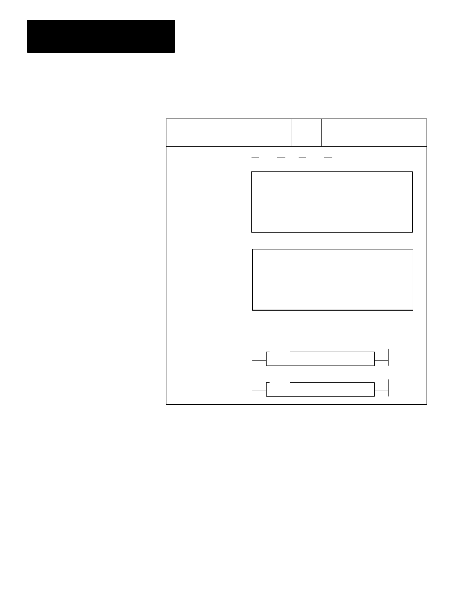
HHT Ladder Display:
HHT Zoom Display:
Ladder Diagrams and APS Displays:
(monitor mode)
F1
F2
F3
F4
F5
ZOOM on STD –(STD)– 2.6.0.0.1
NAME: SELECTABLE TIMED DISABLE
EDT_DAT
F1
F2
F3
F4
F5
ZOOM on STE –(STE)– 2.3.0.0.2
NAME: SELECTABLE TIMED ENABLE
EDT_DAT
STD Selectable Timed Disable – This instruction, when true, will reset the
STI enable bit and prevent the STI subroutine from executing. When the
rung goes false, the STI enable bit remains reset until a true STS or STE
instruction is executed. The STI timer continues to operate while the enable
bit is reset.
STE Selectable Timed Enable – This instruction, upon a false-true
transition of the rung, will set the STI enable bit and allow execution of the
STI subroutine. When the rung goes false, the STI enable bit remains set
until a true STD instruction is executed. This instruction has no effect on the
operation of the STI timer or setpoint. When the enable bit is set, the first
execution of the STI subroutine can occur at any fraction of the timing cycle
up to a full timing cycle later.
STD and STE Instructions