Rockwell Automation 1747-PT1, D1747NP002 Hand-Held Terminal User Manual
Page 357
Chapter 26
PID Instruction
26–13
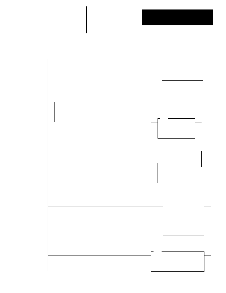
The following ladder diagram shows a typical PID loop that is programmed
in the STI mode. This example (in APS format) is provided primarily to
show the proper scaling techniques. It shows a 4 to 20mA analog input and a
4 to 20mA analog output.
SCL
SCALE
Source
I:1.0
0
Rate [/10000]
12499
Offset
–4096
Dest
N10:28
0
LES
LESS THAN
Source A
I:1.0
0
Source B
3277
GRT
GREATER THAN
Source A
I:1.0
0
Source B
16384
MOV
MOVE
Source
3277
Dest
I:1.0
0
IIM
IMMEDIATE IN w MASK
Slot
I:1.0
Mask
FFFF
(L)
B3
0
This rung immediately updates the analog input used for PV.
Rung 3:0
Rung 3:1
Rung 3:2
Rung 3:3
Rung 3:4
These two rungs ensure the analog input value to be scaled remains within the limits of 3277 to 16384. This is necessary to
prevent “out of range” conversion errors in both the SCL and PID instructions. The latch bits can be used elsewhere in your
program to identify the particular out of range condition that occurred.
Under range
MOV
MOVE
Source
16384
Dest
I:1.0
0
(L)
B3
1
Over range
The source to be scaled is the input I:1 and its destination is the process variable of the PID instruction. These values are
calculated knowing that the input range is 3277 to 16384, while the scaled range (PV) is 0 to 16383.
PID
PID
Control Block
N10:0
Process Variable
N10:28
Control Variable
N10:29
Control Block Length
23