Data file displays, Output file (o0), Input file (i1) – Rockwell Automation 1747-PT1, D1747NP002 Hand-Held Terminal User Manual
Page 191
Monitoring Controller Operations
Chapter 12
12–5
The following section provides you with an example of what each data table
display appears as. The radix (or number system) that the file elements are
displayed in is fixed: binary for Input, Output, and Bit files; decimal for
Integer files; and formatted display for Status, Timer, Counter, and Control
files.
To access the data table, place the cursor on the left power rail in the online
monitor display and press [
F3
], EDT_DAT. The first file in the data table
appears, the output data file.
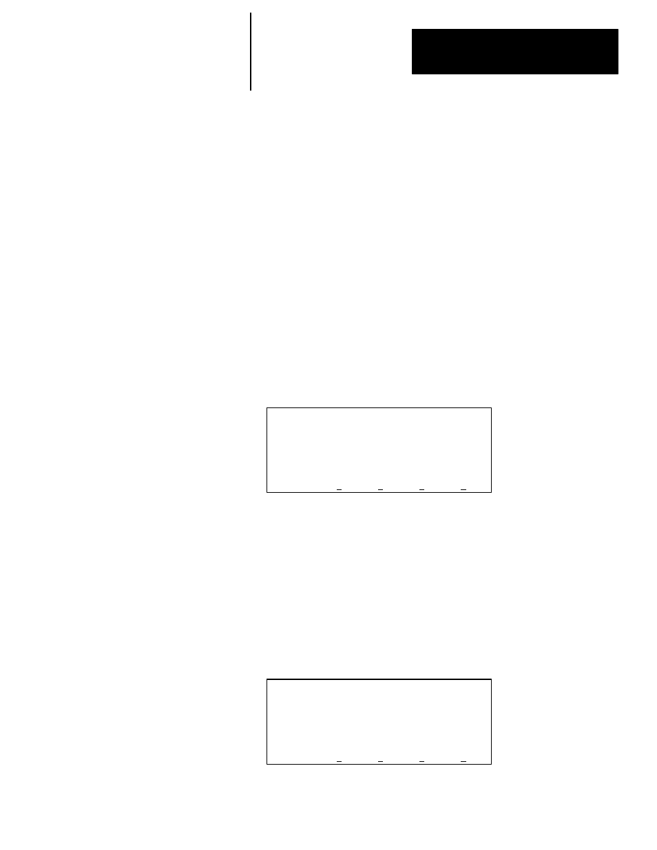
Output File (O0)
The output data file displays the elements that correspond to the specified
controller I/O configuration. The following output file display indicates that
there is an 8–point output module in slot 3. Each bit in the word represents
the On/Off status of an output circuit or terminal. All bits are presently reset
(0).
Important: If the processor is in the Run mode, you can only save changed
data in the output file if you have a SLC 5/02 processor and
your file was saved allowing this option. Refer to chapter 8.
ADDRESS NEXT FL PREV FL NEXT PG PREV PG
F1
F2
F3
F4
F5
Address 15 data 0
O0:3.0 0000 0000
O0:3.0/0 = 0 RUN
To display the next consecutive data file – the input data file, press [
F2
],
NEXT_FL.
Input File (I1)
The input data file displays the elements that correspond to the specified
controller I/O configuration. The following input file display indicates that
there is a 4–point input module in slot 1 and an 8–point input module in slot
2. Each input slot is shown as a word/element address. Each bit in the word
represents the On/Off status of an input circuit or terminal. All bits are
presently reset (0).
ADDRESS NEXT FL PREV FL NEXT PG PREV PG
F1
F2
F3
F4
F5
Address 15 data 0
I1:1.0 0000
I1:2.0 0000 0000
I1:1.0/0 = 0 RUN
Data File Displays