Rockwell Automation 1747-PT1, D1747NP002 Hand-Held Terminal User Manual
Page 62
Chapter 4
Data File Organization and Addressing
4–6
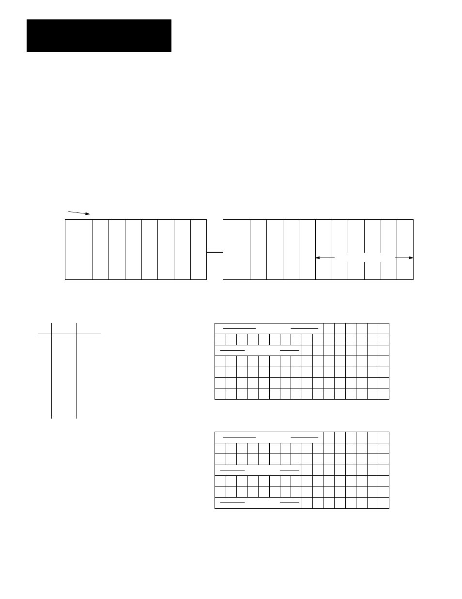
I/O Addressing for a Modular Controller: With modular controllers, slot
number 0 is reserved for the processor module (CPU). Slot 0 is invalid as an
I/O slot.
The figure below shows a modular controller configuration consisting of a
7-slot rack interconnected with a 10-slot rack. Slot 0 contains the CPU.
Slots 1 through 10 contain I/O modules. The remaining slots are saved for
future I/O expansion.
The figure indicates the number of inputs and outputs in each slot and also
shows how these inputs and outputs are arranged in the data files. For these
files, the element size is always 1 word.
Slot Numbers
CPU
I/O
I/O
0
1
2
Power
Supply
I/O
I/O
3
4
I/O
I/O
5
6
I/O
I/O
7
8
Power
Supply
I/O
I/O
9
10
Future Expansion
Modular controller using a 7–slot rack interconnected with a 10–slot rack.
2
3
6
32
None
6
None
16
Slot
Inputs Outputs
4
5
6
7
8
9
10
8
None
16
16
8
None
None
8
32
None
None
None
16
16
1
Data File 0 – Output Image
0
1
2
3
4
5
6
7
8
9
10
11
12
13
14
15
X
INVALID
Slot 1 outputs (0–5)
Slot 3 outputs (0–15)
Slot 4 outputs (0–7)
Data File 1 – Input Image
0
1
2
3
4
5
6
7
8
9
10
11
12
13
14
15
X
Slot 1 inputs (0–5)
Slot 2, word 0 inputs (0–15)
Slot 2, word 1 inputs (0–15)
O:1
O:3
O:4
I:1
I:2
I:2.1
See Addressing “Examples,” next page.
X
Slot 5, word 0 outputs (0–15)
Slot 5, word 1 outputs (0–15)
Slot 9 outputs (0–15)
Slot 10 outputs (0–15)
Slot 4 inputs (0–7)
X
Slot 6 inputs (0–15)
Slot 7 inputs (0–15)
Slot 8 inputs (0–7)
X
INVALID
INVALID
INVALID
INVALID
I:4
I:6
I:7
I:8
O:5
O:5.1
O:9
O:10