Iid/iie zone example – Rockwell Automation 1747-PT1, D1747NP002 Hand-Held Terminal User Manual
Page 438
5/02 Processor Only
Chapter 31
Understanding I/O Interrupts –
31–8
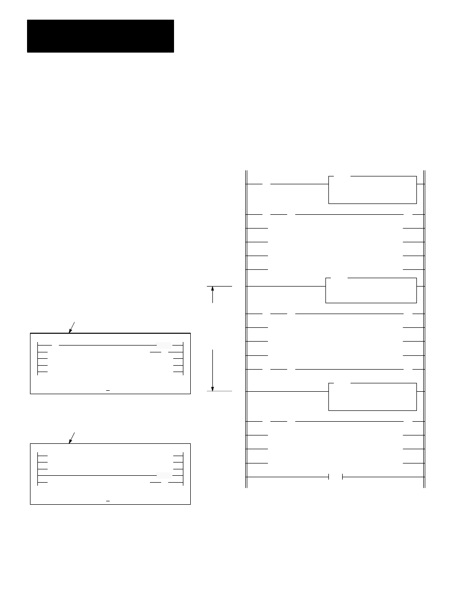
IID/IIE Zone Example
In the program below, slots 1, 2, and 7 are capable of generating I/O
interrupts. The IID and IIE instructions in rungs 6 and 12 are included to
avoid having I/O interrupt ISRs execute as a result of interrupt requests from
slots 1, 2, or 7. This allows rungs 7 through 11 to execute without
interruption.
] [
S:1
15
( )
ISR execution
will not occur
between IID
and IIE
instructions
END
0
] [
] [
( )
] [
] [
( )
] [
] [
( )
] [
] [
1
2
3
4
5
6
7
8
9
10
11
12
13
14
15
16
17
Program File 2
IID
I/O INTERRUPT DISABLE
Slots:
1,2,7
IIE
I/O INTERRUPT ENABLE
Slots:
1,2,7
IIE
I/O INTERRUPT ENABLE
Slots:
1,2,7
The first pass bit S:1/15 and the IIE instruction in rung 0 are
included to insure that the I/O interrupt function is initialized
following a power cycle. You should include a rung such as this
any time your program contains an IID/IIE zone or an IID
instruction.
The IID instruction in rung 6 clears the I/O interrupt enable bits
associated with slots 1, 2, and 7 (S:27/1, S:27/2, and S:27/7).
The IIE instruction in rung 12 sets these same bits. If an I/O
interrupt is detected by the processor while the processor is
executing rungs 7–11, the interrupt will be marked as pending
(S:25/1, S:25/2, and/or S:25/7 will be set). All interrupts marked
as pending will be serviced upon execution of rung 12 (the
lowest numbered slot is serviced first when multiple pending bits
are set).
] [
RUN
MODE FORCE EDT DAT SEARCH
F1
F2
F3
F4
F5
IIE:0110 0001... 2.0.0.0.2
(IIE)
( )
RUN
MODE FORCE EDT DAT SEARCH
F1
F2
F3
F4
F5
IID:0001 1110... 2.6.0.0.1
(IID)
( )
When the cursor is on the IIE instruction,
the enabled slots are indicated here by 1s.
When the cursor is on the IID instruction, the
disabled slots are indicated here by 0s.
HHT Ladder Display: