5motor control (mctrl) – Lenze 8400 HighLine User Manual
Page 276
5
Motor control (MCTRL)
5.11
Encoder/feedback system
276
Lenze · 8400 HighLine · Referenzhandbuch · DMS 10.0 EN · 06/2014 · TD05/TD14
_ _ _ _ _ _ _ _ _ _ _ _ _ _ _ _ _ _ _ _ _ _ _ _ _ _ _ _ _ _ _ _ _ _ _ _ _ _ _ _ _ _ _ _ _ _ _ _ _ _ _ _ _ _ _ _ _ _ _ _ _ _ _ _
General procedure
(if the encoder is connected to the digital inputs DI1 and DI2)
1. Define the function of the digital inputs DI1 and DI2 in
.
2. Set the encoder increments in
3. Select "1: Encoder signal FreqIn12" in
4. Adapt the filter time of the speed measurement in
5. In the case of encoders with a very low resolution (number of increments < 120 increments):
Change the encoder evaluation procedure in
if necessary.
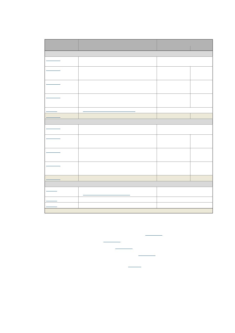
Settings for HTL encoder at DI1/DI2
Fct. DI 1/2 200kHz
• Function of the digital inputs DI1 and DI2
0: DI1(6)=In / DI2(7)=In
FreqIn12: Encoder increment
• If the digital inputs DI1 and DI2 are used as
encoder inputs.
128 Incr./rev.
FreqIn12: Encoder scanning time
• If the digital inputs DI1 and DI2 are used as
encoder inputs.
10 ms
FreqIn12: Encoder filter time
• If the digital inputs DI1 and DI2 are used as
encoder inputs.
1.0 ms
Encoder evaluation method DigIn12 ( 279)
2: Comb. encoder method
Actual value - HTL encoder FreqIn12
- rpm
Settings for HTL encoder at DI6/DI7
Fct. DI 6/7 10kHz
• Function of the digital inputs DI6 and DI7
0: DI1(6)=In / DI2(7)=In
FreqIn67: Encoder increment
• If the digital inputs DI6 and DI7 are used as
encoder inputs.
128 Incr./rev.
FreqIn67: Encoder scanning time
• If the digital inputs DI6 and DI7 are used as
encoder inputs.
10 ms
FreqIn67: Encoder filter time
• If the digital inputs DI6 and DI7 are used as
encoder inputs.
1.0 ms
Actual value - HTL encoder FreqIn67
- rpm
Monitoring
Resp. open circuit HTL encoder
Encoder open-circuit monitoring ( 307)
1: Fault
Resp. max. speed/output freq. reached
0: No Reaction
Resp. to max. freq. feedb. DIG12/67
1: Fault
Parameter
Info
Lenze setting
Value Unit
Highlighted in grey = display parameter