Rejoining a node to the cluster, Replacing a node in a logical chassis cluster – Brocade Network OS Administrator’s Guide v4.1.1 User Manual
Page 79
standalone mode.) If the no vcs logical-chassis enable command is executed on a switch that is
currently in logical chassis cluster mode, the switch boots in fabric cluster mode.
Once the node is removed, all configurations corresponding to that node are removed from the cluster
configuration database. Similarly, the removed node does not retain any configurations corresponding
to the other nodes in the cluster.
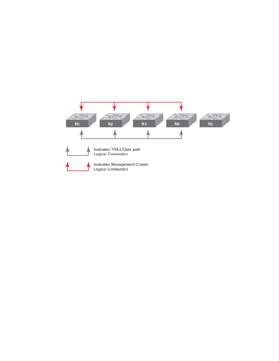
The following shows the cluster after node N5 has been removed. Nodes N1 through N4 remain in the
cluster, and N5 is an island. There is no data path or management path connectivity between the two
islands.
FIGURE 13 Removal of Node N5 from the logical chassis cluster
Rejoining a node to the cluster
Nodes that are temporarily isolated from a logical chassis cluster can re-join the cluster as long as no
configuration or cluster membership changes have taken place on either the deleted node or the
cluster. Run the vcs logical-chassis enable command with the desired options to rejoin the node to
the cluster.
However, if configuration changes have occurred on either the node or cluster since the node was
removed, you must reboot the node with its default configuration by issuing copy default-config
startup-config on the segmented node.
Replacing a node in a logical chassis cluster
If a node in a logical chassis cluster becomes damaged and no longer be used, a similar node with
identical capabilities can be used in its place.
The new node must use the same RBridge ID of the node that is being replaced. When the new node is
detected, it joins the cluster as a previously known node instead of being considered a new node.
To replace a node that has an RBridge ID of 3 and then enter the WWN of the new node, follow the
steps shown in the following example:
1. Run the following command on the principal switch:
switch# vcs replace rbridge-id 3
Enter the WWN of the new replacement switch: 11:22:33:44:55:66:77:81
2. Assign the RBridge ID of 3 to the new node by running the following command on the new node,
assuming the new node is already VCS enabled:
switch# vcs rbridge-id 3
Rejoining a node to the cluster
Network OS Administrator’s Guide
79
53-1003225-04