Brocade Network OS Administrator’s Guide v4.1.1 User Manual
Page 715
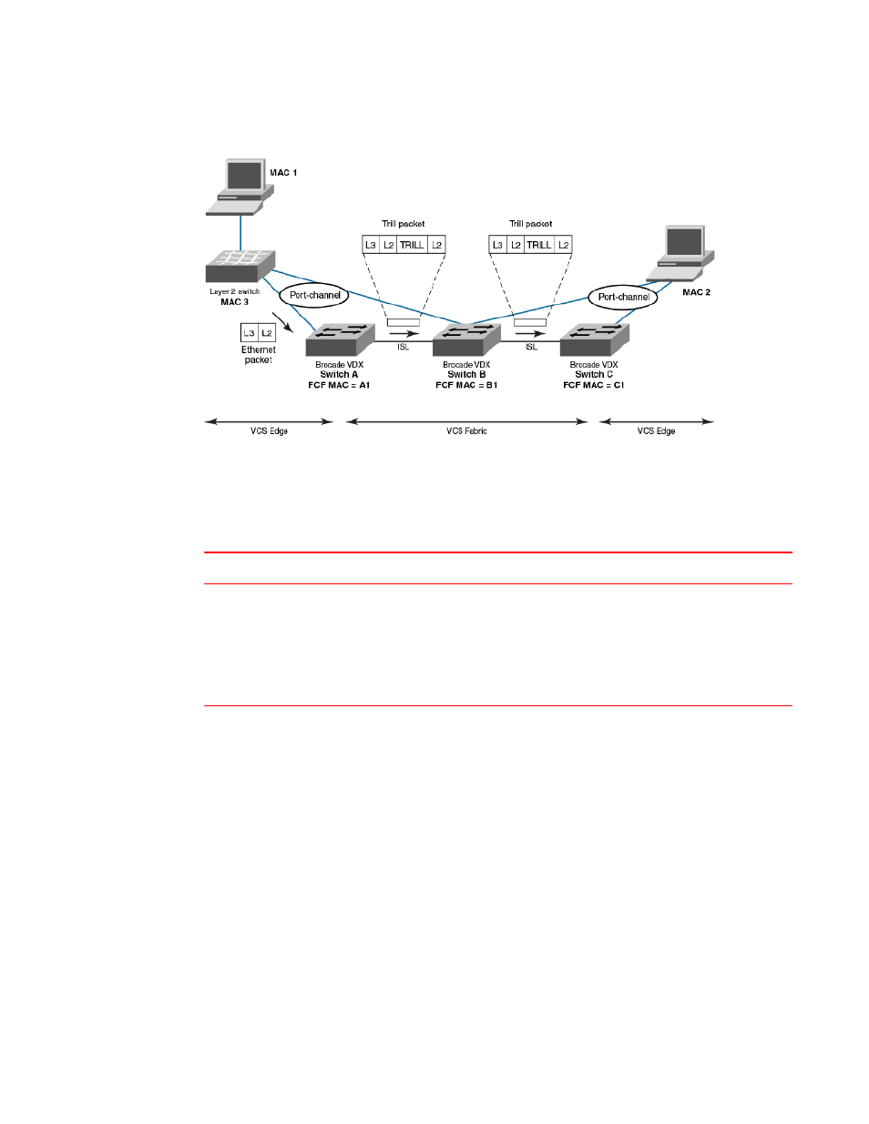
FIGURE 78 Normal Layer 2 packet traversing a VCS fabric
In the figure above, an Ethernet packet arrives from MAC 1 at the VCS fabric edge. TRILL header
information is added while the packet passes through the VCS fabric. The TRILL information is removed
on leaving the VCS fabric, and a regular Ethernet packet arrives at MAC 2. The table below shows the
Layer 2 packet header details.
Packet header details — Layer 2 packer traverses VCS fabric
TABLE 101
Ethernet packet
TRILL packet — first hop
TRILL packet — second hop
L2 DA = MAC 2L2
SA = MAC 1
Outer L2 DA = B1Outer L2 SA =
A1Outer 802.1q tagOuter etype =
TRILLTRILL destination RBridge ID =
CTRILL source RBridge ID = ATRILL
flagsInner L2 DA = MAC 2Inner L2 SA
= MAC 1
Inner 802.1q tagInner etype = 0x800
Outer L2 DA = C1Outer L2 SA = B1Outer 802.1q
tagOuter etype = TRILLTRILL destination RBridge
ID = CTRILL source RBridge ID = ATRILL flagsInner
L2 DA = MAC 2Inner L2 SA = MAC 1
Inner 802.1q tagInner etype = 0x800
When viewing packets while using the l2traceroute command, notice the TRILL OAM header
information added to the packets as they traverse the VCS Fabric. Starting the trace on Switch A, TRILL
OAM first verifies path continuity with its immediate neighbor, in this case Switch B. It does this as
shown in the figure below, by sending a Layer 2 traceroute request packet with the time-to-live (TTL)
TRILL attribute set to 1. Switch B replies with reachability information regarding the next hop.
Troubleshooting procedures
Network OS Administrator’s Guide
715
53-1003225-04