Link state advertisements, Virtual links – Brocade Network OS Administrator’s Guide v4.1.1 User Manual
Page 588
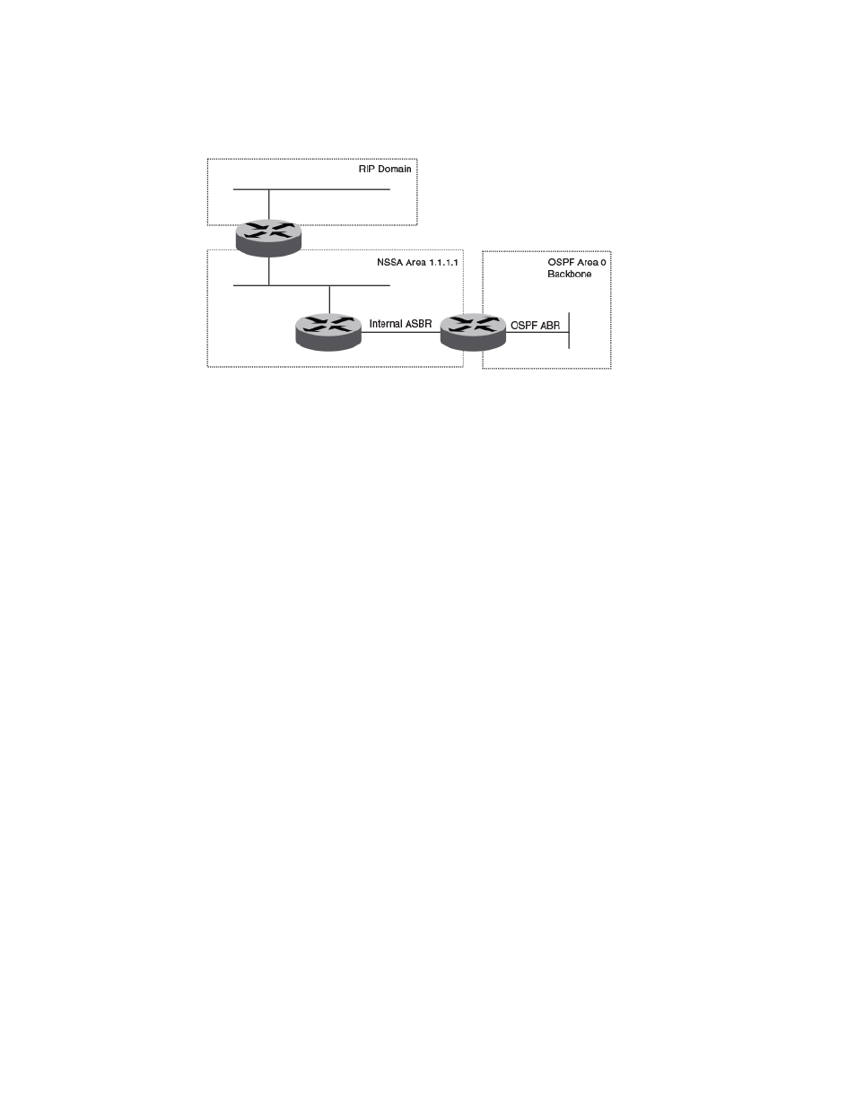
FIGURE 63 OSPF network containing an NSSA
This example shows two routing domains, a RIP domain and an OSPF domain. The ASBR inside the
NSSA imports external routes from RIP into the NSSA as Type 7 LSAs, which the ASBR floods
throughout the NSSA.
The ABR translates the Type 7 LSAs into Type 5 LSAs. If a summary-address is configured for the
NSSA, the ABR also summarizes the LSAs into an aggregate LSA before flooding the Type 5 LSAs
into the backbone.
Because the NSSA is partially stubby the ABR does not flood external LSAs from the backbone into
the NSSA. To provide access to the rest of the Autonomous System (AS), the ABR generates a
default Type 7 LSA into the NSSA.
Link state advertisements
Communication among areas is provided by means of link state advertisements (LSAs). The LSAs
supported for each area type are as follows:
• Backbone (area 0) supports LSAs 1, 2, 3, 4, 5, and 7.
• Nonbackbone, not stub area supports LSAs 1, 2, 3, 4, and 5.
• Stub area supports LSAs 1, 2, and 3.
• Totally stubby area (TSA) supports LSAs 1 and 2, and also supports a single LSA 3 per ABR,
advertising a default route.
• No so stubby area (NSSA) supports LSAs 1, 2, 3, and 7.
Virtual links
All ABRs must have either a direct or indirect link to the OSPF backbone area (0.0.0.0 or 0). If an ABR
does not have a physical link to the area backbone, the ABR can configure a virtual link to another
router within the same area, which has a physical connection to the area backbone.
The path for a virtual link is through an area shared by the neighbor ABR (router with a physical
backbone connection), and the ABR requires a logical connection to the backbone.
Two parameters fields must be defined for all virtual links — transit area ID and neighbor router:
• The transit area ID represents the shared area of the two ABRs and serves as the connection point
between the two routers. This number should match the area ID value.
• The neighbor router field is the router ID (IP address) of the router that is physically connected to
the backbone, when assigned from the router interface requiring a logical connection. When
assigning the parameters from the router with the physical connection, be aware that the router ID
is the IP address of the router requiring a logical connection to the backbone.
Link state advertisements
588
Network OS Administrator’s Guide
53-1003225-04