Brocade Network OS Administrator’s Guide v4.1.1 User Manual
Page 73
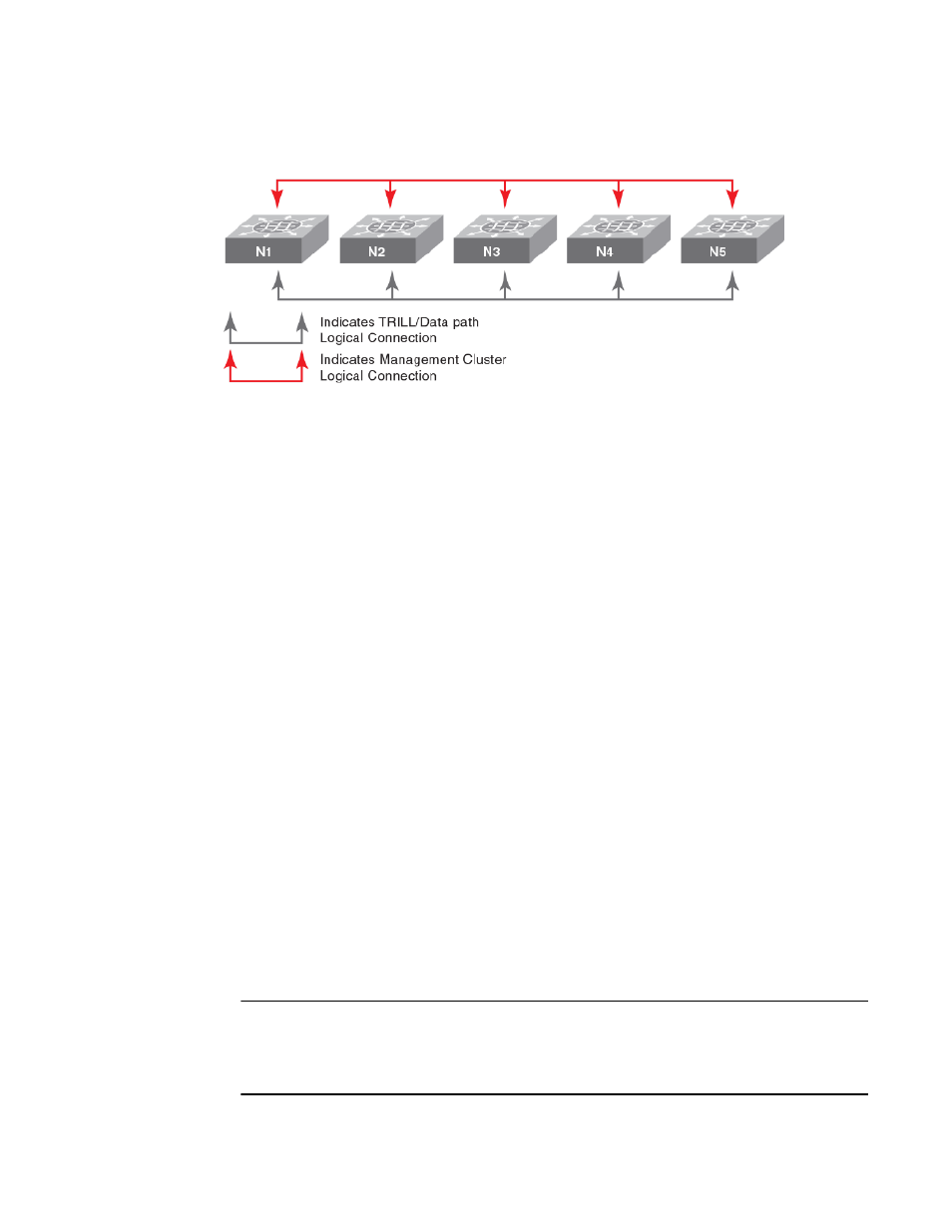
FIGURE 12 Five-node logical chassis cluster
To create a logical chassis cluster, follow the steps in the example below:
1. Log into one switch that will be a member of the logical chassis cluster you are creating:
2. In privileged EXEC mode, enter the vcs command with options to set the VCD ID, the RBridge ID
and enable logical chassis mode for the switch. The VCS ID and RBridge IDs shown below are
chosen for the purposes of this example.
switch# vcs vcsid 22 rbridge-id 15 logical-chassis enable
3. The switch reboots after you run the vcs command. You are asked if you want to apply the default
configuration; answer yes.
4. Repeat the above steps for each node in the cluster, changing only the RBridge ID each time. You
must, however, set the VCS ID to the same value on each node that belongs to the cluster.
5. When you have enabled the logical chassis mode on each node in the cluster, run the show vcs
command to determine which node has been assigned as the cluster principal node. The arrow (>)
denotes the principal node. The asterisk (*) denotes the current logged-in node.
switch# show vcs
Config Mode : Distributed
VCS Mode : Logical Chassis
VCS ID : 44
VCS GUID : bcab366e-6431-42fe-9af1-c69eb67eaa28
Total Number of Nodes : 3
Rbridge-Id WWN Management IP VCS Status Fabric Status
HostName
--------------------------------------------------------------------------------------------------------
------
144 10:00:00:27:F8:1E:3C:8C 10.18.245.143 Offline Unknown
sw0
152 >10:00:00:05:33:E5:D1:93* 10.18.245.152 Online Online
cz41-h06-m-r2
158 10:00:00:27:F8:F9:63:41 10.18.245.158 Offline Unknown
sw0
The RBridge ID with the arrow pointing to the WWN is the cluster principal. In this example, RBridge
ID 154 is the principal.
6. Set the clock and time zone for the principal node. Time should be consistent across all the nodes.
Network Time Protocol overview
on page 97.
7. Log in to the principal cluster and make any desired global and local configuration changes. These
changes then are distributed automatically to all nodes in the logical chassis cluster.
NOTE
You can enter the RBridge ID configuration mode for any RBridge in the cluster from the cluster
principal node. You can change the principal node by using the logical-chassis principal priority
and logical chassis principal switchover commands. For more information about cluster principal
nodes, refer to
Selecting a principal node for the cluster
on page 77.
Basic Switch Management
Network OS Administrator’s Guide
73
53-1003225-04