Ospf over vrf, Ospf in a vcs environment, Ospf over vrf ospf in a vcs environment – Brocade Network OS Administrator’s Guide v4.1.1 User Manual
Page 589
NOTE
By default, a device’s router ID is the IP address configured on the lowest numbered loopback interface.
If the device does not have a loopback interface, the default router ID is the lowest numbered IP
address configured on the device. When you establish an area virtual link, you must configure it on both
of the routers (both ends of the virtual link).
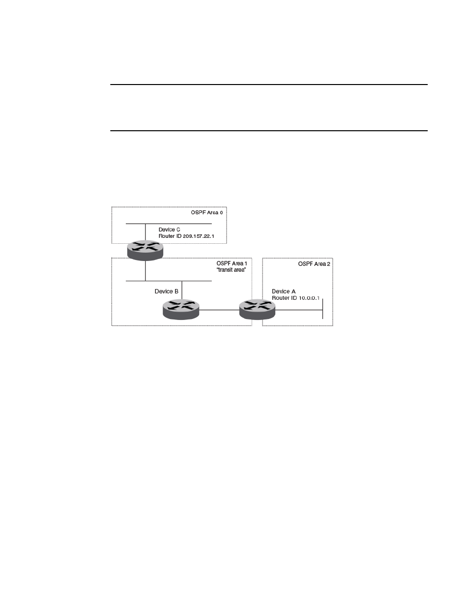
The figure below shows an OSPF area border router, Device A, that is cut off from the backbone area
(area 0). To provide backbone access to Device A, you can add a virtual link between Device A and
Device C using area 1 as a transit area. To configure the virtual link, you define the link on the router
that is at each end of the link. No configuration for the virtual link is required on the routers in the transit
area.
FIGURE 64 Defining OSPF virtual links within a network
OSPF over VRF
With Network OS 4.0 and later, OSPF can run over multiple Virtual Routing and Forwarding (VRF)
instances. OSPF maintains multiple instances of the routing protocol to exchange route information
among various VRF instances. A multi-VRF-capable router maps an input interface to a unique VRF,
based on user configuration. These input interfaces can be physical or a switched virtual interface (SVI).
By default, all input interfaces are attached to the default VRF instance. All OSPF commands supported
in Network OS 4.0 and later are available over default and nondefault OSPF instances.
OSPF in a VCS environment
The figure below shows one way in which OSPF can be used in a VCS fabric cluster environment.
Routers RB1 and RB2, as well as the MLX switches, are configured with OSPF. Switches RB3, RB4,
and RB5 are Layer 2 switches.
OSPF over VRF
Network OS Administrator’s Guide
589
53-1003225-04