IAI America TT-C3 User Manual
Page 41
31
INTELLIGENT ACTUATOR
Chapter 1 Installation
2.
Speci
¿
cations
(4) Use example
The following is a setting example of assigning the system IOs to external DIOs as shown below
when the external DIOs are assigned to input port Nos. 16 to 31 and output port Nos. 316 to 331
(default settings: the external DIOs are normally assigned to these ports before shipment).
Settings that allow the panel window LEDs (RDY, ALM, EMG, HPS) to continue functioning
normally are explained.
Input port No. 16 = Program start number (ON edge) (specified by BCD)
Input port No. 17 = Servo ON signal
Input port Nos. 18 to 23 = Start program number
Input port No. 24 = Error reset (ON edge)
Input port No. 25 = Home return of all valid axes (ON edge)
Output port No. 316 = Error of operation-cancellation level or higher (ON)
Output port No. 317 = READY output (PIO trigger program operation permitted)
Output port No. 318 = Emergency stop output (ON)
Output port No. 319 = Output during automatic operation
Output port No. 320 = Output if all valid axes completed home return (coordinates have been
confirmed)
Output port Nos. 321 to 323 = Output when axis 1 to 3 servos are ON
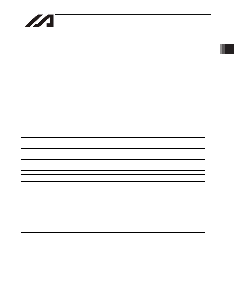
I/O Parameter Settings
No. Parameter
name
Settings
Remarks
30
Input function selection 000
1
1 (default value) = Program start signal (ON edge)
(specified by BCD)
32
Input function selection 002
1
1 = Servo ON
37
to 42
Input function selection 007 to 012
1
1 (default value) = Start program number
43
Input function selection 013
2
2 = Error reset (ON edge)
45
Input function selection 015
1
1 = Home return of all valid axes (ON edge)
283
Physical input port number for input function selection 000
16
Input port number = 16
285
Physical input port number for input function selection 002
17
Input port number = 17
290
to 295
Physical input port number for input function selection 007 to
physical input port number for input function selection 012
18
to 23
Input port number = 18 to 23
296
Physical input port number for input function selection 013
24
Input port number = 24
298
Physical input port number for input function selection 015
25
Input port number = 25
315
to 330
Physical input port number for output function selection 300
(area 2) to physical input port number for output function
selection 307 (area 2)
316
to 323
Output port numbers = 316 to 323
331
Output function selection 300 (area 2)
1
1 = Error of operation-cancellation level or higher
(ON)
332
Output function selection 301 (area 2)
1
1 = READY output
(PIO trigger program operation permitted)
333
Output function selection 302 (area 2)
1
1 = Emergency stop output (ON)
334
Output function selection 303 (area 2)
2
2 = Output during automatic operation
(Other parameter No. 12)
335
Output function selection 304 (area 2)
2
2 = Output if all valid axes completed home return
(coordinates have been confirmed)
336
to 338
Output function selection 305 (area 2) to output function
selection 307 (area 2)
2
2 = Output when axis 1 to 3 servos are ON
(system monitor task output)
[Notes]
x If input function selection 000 (start) is assigned to a different input port, the start switch on the
front panel will no longer function as the “program start signal.”
x If any of input function selections 007 to 013 (digital switches) is assigned to a different input
port, the digital program selector switch on the front panel will no longer function as the “start
program number.”