Driver card parameters, Appendix – IAI America TT-C3 User Manual
Page 314
304
INTELLIGENT ACTUATOR
Appendix
Appendix
Driver Card Parameters
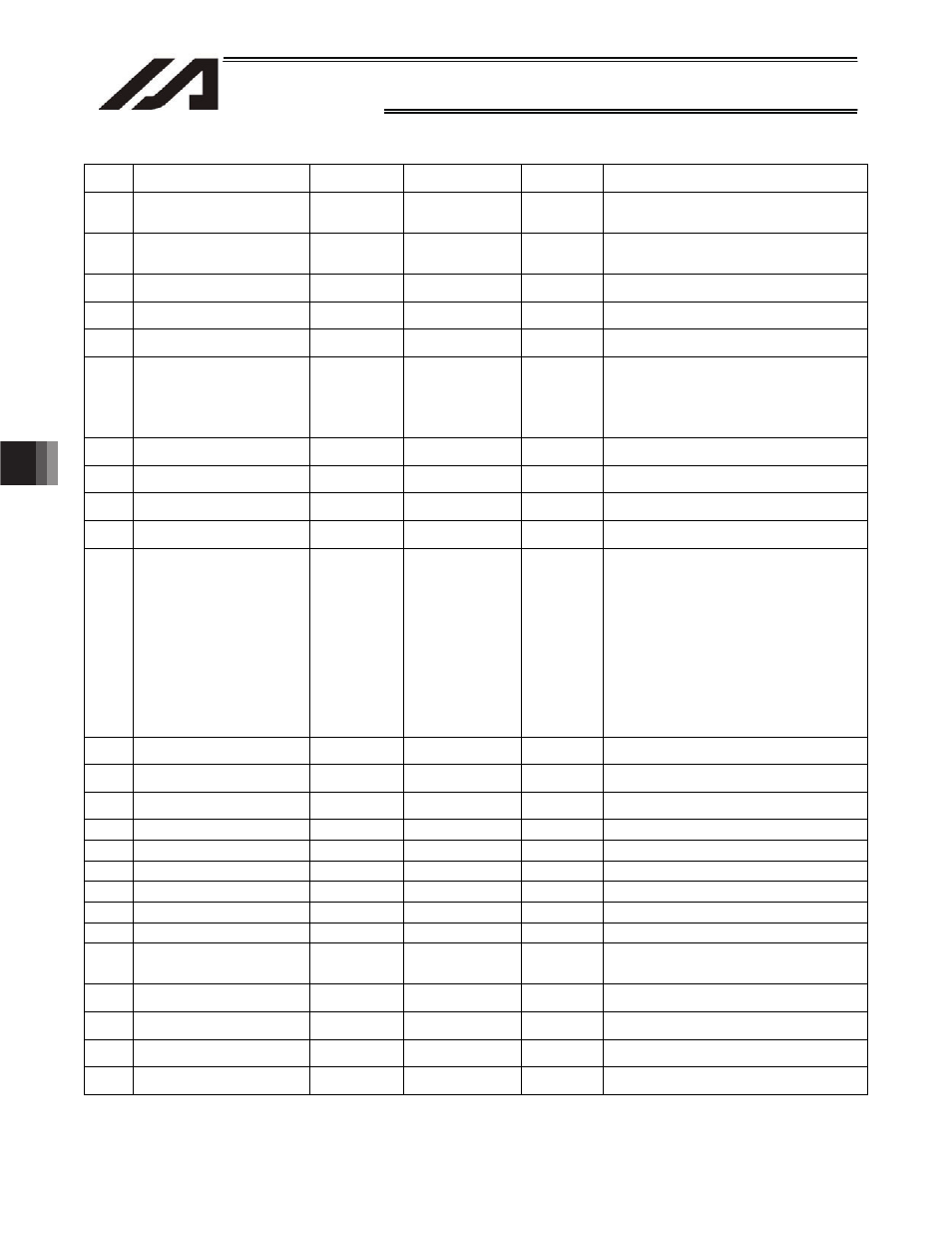
No Parameter
name
Default value
(Reference)
Input range
Unit
Remarks
24 Configuration
information
02:
Configured voltage (motor
voltage)
0018H Reference
only
25 Configuration
information
03:
Motor/encoder configuration
information
0500H Reference
only
Motor/encoder
ID bit number
26 Configuration
information
04:
For future expansion
0000H
Reference only
For adjustment by the manufacturer
27 Configuration
information
05:
Encoder resolution (upper word)
0000H Reference
only
28 Configuration
information
06:
Encoder resolution (lower word)
0320H Reference
only
29 Configuration
information
07:
Motor/encoder characteristics
word
0004H
Reference only
Bit 0: Change prohibited (0: Rotary)
Bit 1: Change prohibited (0: Incremental)
Bit 2: Change prohibited
(1: Magnetic sensor equipped)
Bit 3: Brake equipment bit
(1: Equipped, 0: Not equipped)
30 Configuration
information
08:
For future expansion
0000H
Reference only
For adjustment by the manufacturer
31 Configuration
information
09:
Control characteristics word
0000H
Reference only
For adjustment by the manufacturer
32 Configuration
information
10:
Push torque limit at home return
40
0 to 150
%
33 Configuration
information
11:
Push torque limit at positioning
70
0 to 70
%
34 Configuration
information
12:
Control characteristics word 2
300H
0000 to FFFF
Bits 0 to 7: For future expansion
Bit 8:
Initial moving direction in excitation-
phase signal detection operation
(0: CW, 1: CCW)
Bit 9:
Stop mode selection
(0: Full servo mode, 1: Complete stop
mode)
* In the case of coating or other application
where operation focus is given to the locus,
select “0” (full servo mode).
(In this case, the complete stop function is
disabled.)
In all other applications, “1” (complete stop
mode) is normally selected.
35 Configuration
information
13:
For future expansion
0H Reference
only
36 Configuration
information
14:
For future expansion
0H Reference
only
37 Configuration
information
15:
For future expansion
0H
Reference only
For adjustment by the manufacturer
38
For future expansion
0H
Reference only
39
For future expansion
0H
Reference only
40
For future expansion
0H
Reference only
41
For future expansion
0H
Reference only
42
Torque filter time constant
0H
0 to 2500
43
For future expansion
0H
Reference only
44
Speed-loop proportional gain
time constant
(upper word)
0H
0000H to 0000H
For pulse motor
45
Speed loop proportional gain
(lower word)
12CH
0000H to 7530H
For pulse motor
46
Speed loop integral gain
(upper word)
0H
0000H to 0004H
For pulse motor
47
Speed loop integral gain
(lower word)
11F9H
0000H to FFFFH
For pulse motor
48
Excitation-phase fixed mode
parameter
0H
Reference only
For pulse motor (Percentage of rated motor
current)