Dresser radius corner radius entire wheel radius – Rockwell Automation 8520-GUM 9/Series CNC Grinder Operation and Programming Manual Documentation Set User Manual
Page 77
Chapter 3
Offset Tables and Setup
3-5
The dresser radius and corner radius compensation schemes use the same
radius table to store a radius value. The entire wheel radius scheme stores
the entire wheel radius in paramacro variable #5508. Which dresser/wheel
radius compensation scheme to use on your system depends on the current
application of your grinder. See chapter 15 for details on how to properly
implement these schemes.
Dresser/Wheel Radius
Compensation Scheme
Length Offsets
Coordinate System
Offset (G54-G59.3)
Dresser/Wheel Radius
Compensation
Dresser Radius
Shifted on Z and X axis to wheel
control point
Shifted to point on
dresser tip
On radius of diamond
dresser
Corner Radius
Shifted on Z and X axis to wheel
control point
Shifted to point on part
being machined
On radius of wheel corner
where Z and X length
offset is located
Entire Wheel Radius
Shifted on Z to control point of wheel,
Y offset is taken into consideration
with dresser/wheel radius
compensation
Shifted to point on part
being machined
On entire radius of wheel
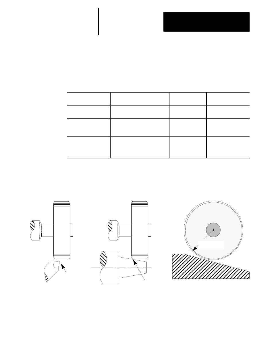
Figure 3.3
Dresser/Wheel Radius Compensation Schemes
Dresser Radius
Corner Radius
Entire Wheel Radius
(common for both cylindrical
and surface grinding applications)
(common for both cylindrical
and surface grinding applications)
(almost exclusively used for surface grinding)
Radius of
dresser tip
Radius of
wheel corner
Radius of
Entire Wheel
11984-I