Rockwell Automation 8520-GUM 9/Series CNC Grinder Operation and Programming Manual Documentation Set User Manual
Page 304
Introduction to Programming
Chapter 10
10-26
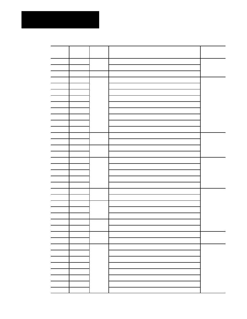
Surface
Grinder
Modal or
Non-modal
Function
Group
Number
Cylindrical
Grinder
G23
G23
04
Programmable Zone 2 and 3 (Off)
Modal
G23.1
G23.1
Programmable Zone
G24
G24
01
Single pass rough facing cycle
G27
G27
00
Machine home return check
Non-modal
G28
G28
Automatic return to machine home
G29
G29
Automatic return from machine home
G30
G30
Return to secondary home
G31
G31
External skip function 1
G31.1
G31.1
External skip function 1
G31.2
G31.2
External skip function 2
G31.3
G31.3
External skip function 3
G31.4
G31.4
External skip function 4
G33
G33
01
Constant lead thread grinding
Modal
G34
G34
Variable lead thread grinding
G36
G36
22
Short block Acc/Dec clamp enable
G36.1
G36.1
Short block Acc/Dec clamp disable
G37
G37
00
Tool gauging skip function # 1
Non-modal
G37.1
G37.1
Tool gauging skip function # 1
G37.2
G37.2
Tool gauging skip function # 2
G37.3
G37.3
Tool gauging skip function # 3
G37.4
G37.4
Tool gauging skip function # 4
G39
G39
20
Dresser/Wheel compensation (linear gen. blocks)
Modal
G39.1
G39.1
Dresser/Wheel radius compensation (circular gen. blocks)
G40
G40
07
Dresser/Wheel radius compensation cancel
G41
G41
Dresser/Wheel radius compensation, left
G42
G42
Dresser/Wheel radius compensation, right
G50.1
G50.1
11
Programmable mirror image cancel
G51.1
G51.1
Programmable mirror image
G52
G52
00
Offset coordinate system zero point
Non-modal
G53
G53
Motion in Machine coordinate system
G54
G54
12
Preset Work Coordinate System 1
Modal
G55
G55
Preset Work Coordinate System 2
G56
G56
Preset Work Coordinate System 3
G57
G57
Preset Work Coordinate System 4
G58
G58
Preset Work Coordinate System 5
G59
G59
Preset Work Coordinate System 6
G59.1
G59.1
Preset Work Coordinate System 7
G59.2
G59.2
Preset Work Coordinate System 8