Assigning wheel length offset values – Rockwell Automation 8520-GUM 9/Series CNC Grinder Operation and Programming Manual Documentation Set User Manual
Page 75
Chapter 3
Offset Tables and Setup
3-3
Important: The first 4 wheel offset numbers (01-04) are reserved for use
in conjunction with an in-process dresser. When the in-process dresser is
disabled, the control automatically updates these first 4 offset numbers
with the current grinding wheel size. These offset values should not be
manually entered. See chapter 21 for details on using the in-process
dressing feature.
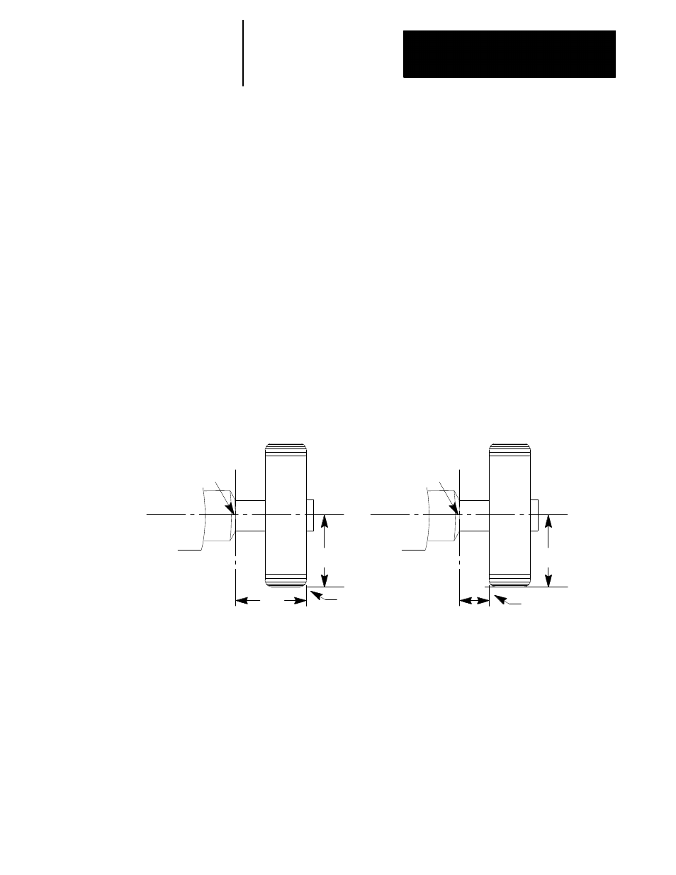
Assigning Wheel Length Offset Values
Use the wheel length offset to compensate for the wheel position as
mounted on the machine. By using the wheel length offset along with
wheel radius and orientation information, a programmer can write a part
program without concern for wheel dimensions and shape. Measure wheel
length values for each axis to define the control point for programming
relative to the wheel gauge point (see Figure 3.2). The same wheel can
have several offset numbers to let the programmer select which part of the
wheel is being controlled.
Figure 3.2
Wheel Length Offsets
Wheel gauge point on
spindle from which wheel
offsets are usually mea-
sured
X length offset
Z
length
offset
X length offset
Z
length
offset
These length offsets
select this point as the
control
point
for
programming
11983-I
Wheel gauge point on
spindle from which wheel
offsets are usually mea-
sured
These length offsets
select this point as the
control
point
for
programming
You can configure each axis on your system to have wheel length offset
values. This manual assumes a two axis Z and X configuration.