The format for the g87 cycle is as follows – Rockwell Automation 8520-GUM 9/Series CNC Grinder Operation and Programming Manual Documentation Set User Manual
Page 602
Cylindrical Grinding Fixed Cycles
Chapter 17
17-28
The format for the G87 cycle is as follows:
G18;
G87Z__X__L__F__E__P__;
Table 17.G summarizes the G87 cycle parameters. For a detailed
description of these parameters, see the text below and page 17-9.
Table 17.G
G87 Cycle Parameters
Parameter:
Definition:
Default Value:
Possible Value:
Plane axis 1
1
plunge end point
value must be programmed
abs. or inc.
Plane axis 2
1
shoulder end point
value must be programmed
abs. or inc.
L
3
number of spark-out revolutions
zero
zero to 999
F
2
plunge feedrate
last feedrate programmed
valid F word
E
3
shoulder feedrate
plunge feedrate
valid F word
P
3 for G87 2 for G87.1
dress program number
from last cycle programmed
valid program number
1
must be programmed
2
must have been programmed in some previous block if omitted
3
optional
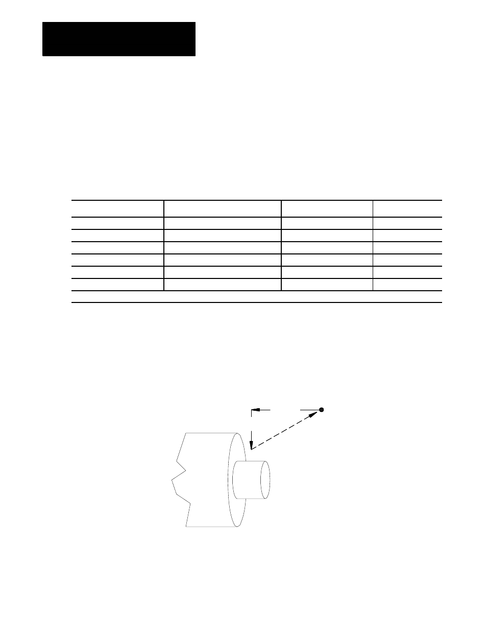
Figure 17.8 shows the axis motions that make up the G87 shoulder
grinding with face plunge cycle. This figure assumes that the ZX plane
(G18) is active.
Figure 17.8
G87 Shoulder Grinding with Face Plunge Motions
X
Part
START
Retract
Z
12058-I
Programming a G87 causes the control to execute two moves to arrive at
the final plunge position. First axis 1 (Z) plunges into the part face at
feedrate F. Then axis 2 (X) makes a shoulder grind at feedrate E.
17.9
G87 or G87.1 Shoulder
Grinding With Face Plunge