Rockwell Automation 8520-GUM 9/Series CNC Grinder Operation and Programming Manual Documentation Set User Manual
Page 491
Dresser/Wheel Radius Compensation
Chapter 15
15-3
Dresser/wheel radius compensation also uses dresser/wheel orientation
data. You need orientation data:
to compensate for inaccuracies that can occur from difficulties in
measuring wheel corner and dresser radius because of mounting
position
and
to tell the control which edge of the dresser/wheel you intend to use
when dressing or grinding
If the above is not a factor, make sure all orientations use an orientation of
0 or 9.
Enter the radius and orientation data into the offset tables before
attempting to activate any compensation. See chapter 3 for details on
entering offset table data.
Types of Dresser/Wheel Radius Compensations
Two types of dresser/wheel radius compensation are available on the
control:
type A (as described on page 15-17)
type B (as described on page 15-27)
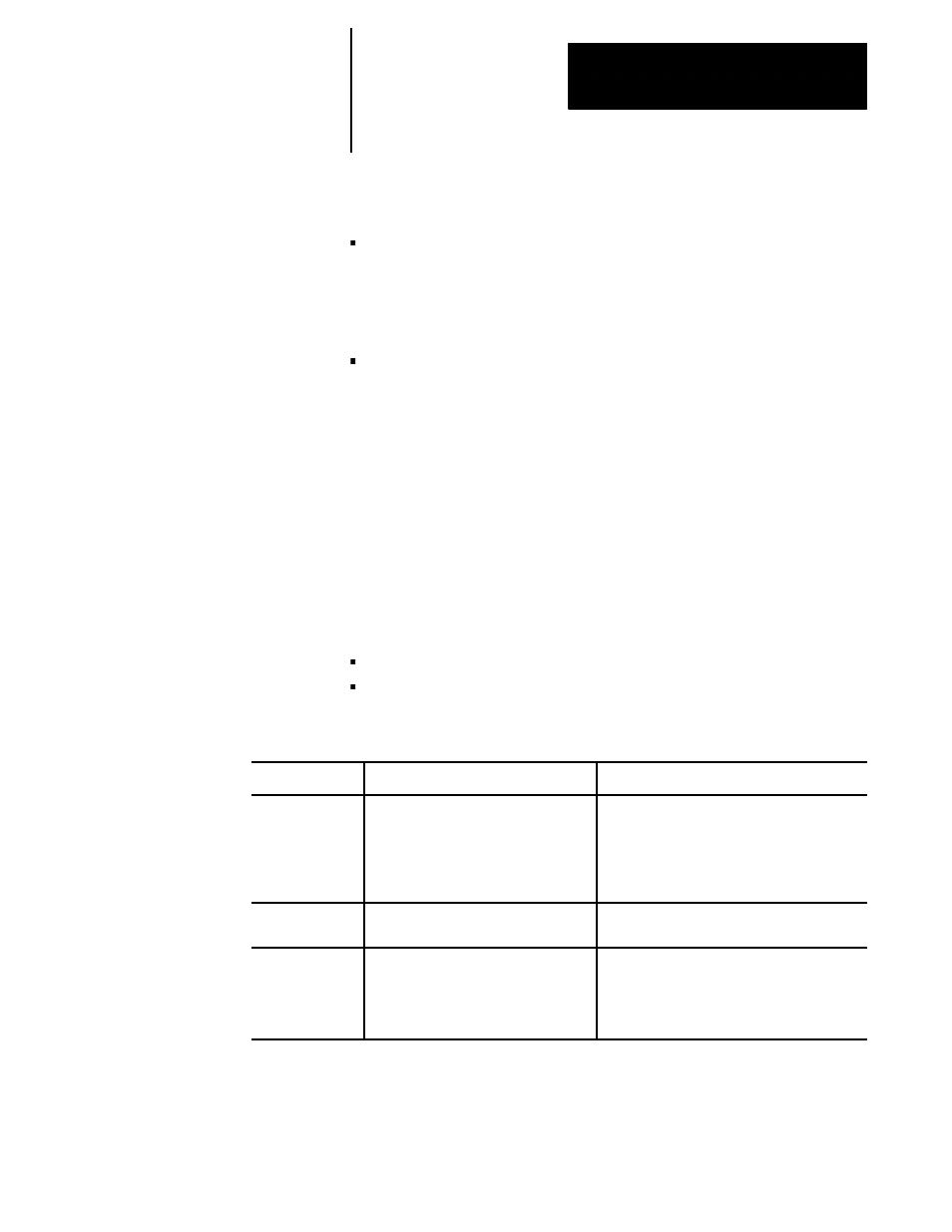
The following table highlights the differences between the two types:
Type of Move
Type A
Type B
Entry Move Into
compensation
The dresser/wheel takes the shortest
possible path to its offset position.
The dresser/wheel stays at least one radius away
from the start-point of the next block at all times.
Extra motion blocks can be generated to attempt
to prevent gouging of the part as can occur in
Type A.
Dresser/wheel
Path
Same as Type B.
Same as Type A.
Exit Move From
compensation
The dresser/wheel takes the shortest path
to the end-point of the exit move for both
inside and outside corners.
The dresser/wheel takes the shortest path to the
end-point of exit move for inside corners only.
For outside corners, the dresser/wheel stays at
least one radius away from the end-point.
Your system installer determines in AMP whether your control uses type A
or type B compensation.